MC1000e-R / T
1-877-313-6418
siskiyou
www.siskiyou.com
5
User’s Manual
4.0 Interface
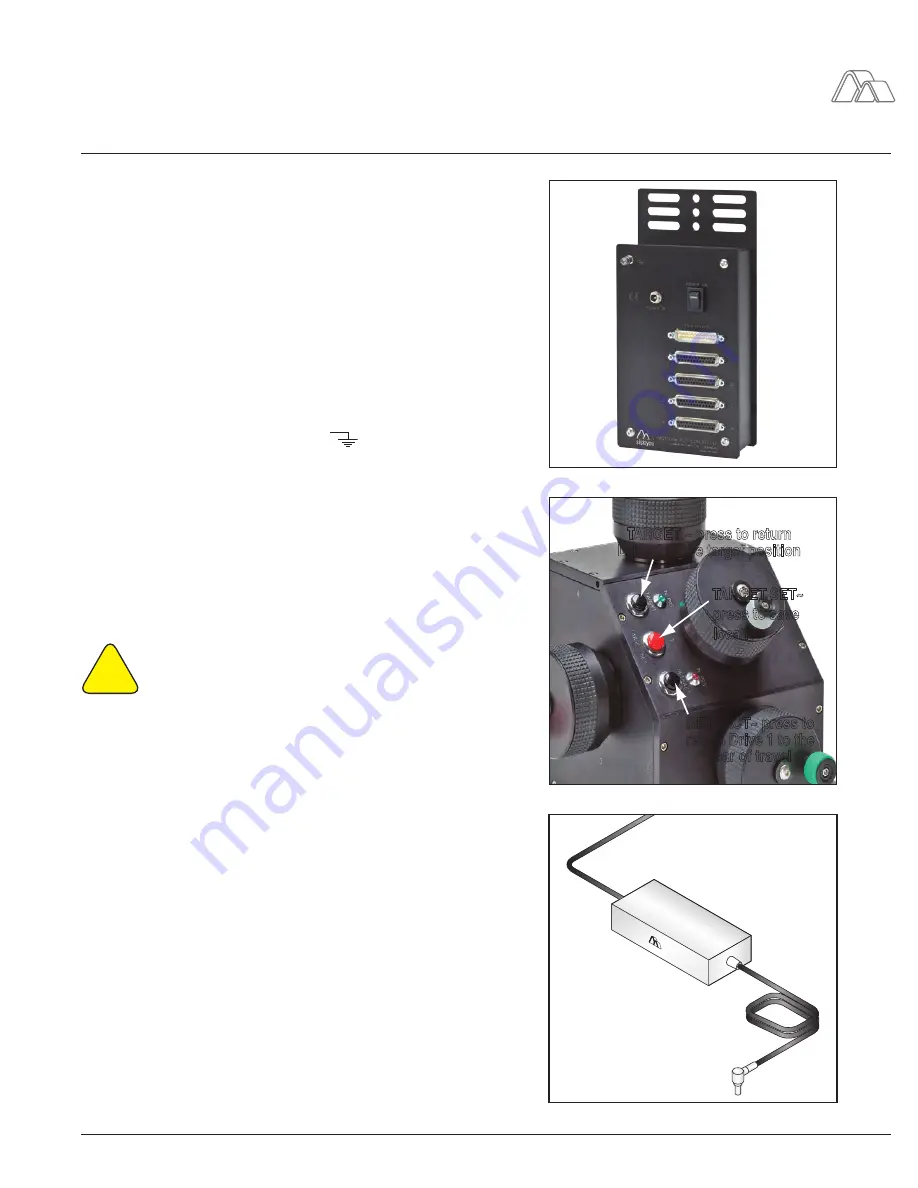
4.1 Junction Box
Power In:
Using the supplied power adapter, the user can connect the
power adapter to the junction box and supply power to the system.
Power Switch:
The power switch turns on the junction box and the control-
ler. This is required to be on in order to use the MC1000e-R/T. Turning off the
power switch will cease all operations with manipulators remaining in place.
The same applies to loss of power.
Ground:
By attaching a wire from the ground lug to a metal surface (that
is not part of the experimental system), the user helps prevent damage from
static shock and to ensure noise-free operation while in use. The lug is repre-
sented by the electrical symbol for “ground”:
Controller:
The 25 pin, male connector, is used for connecting the controller
to the junction box. Only use the supplied cable for this connection.
1, 2, 3, and 4 Ports:
The 25 pin, female connectors, are used for connect-
ing the motor drive cables to the junction box. A motor drive must be plugged
into port 1 for the MC1000e-R/T to work.
4.2 Controller
!
CAUTION: MAKE SURE THAT THE FOLLOWING STEPS OF
INSTRUCTIONS CONCERNING TARGET SET, RETRACT, AND
TARGET BUTTON FEATURES ARE FOLLOWED TO AVOID AN
UNWANTED COLLISION TO YOUR SETUP.
Drive Axis No. 1, 2, 3, and 4:
These four knobs are color coded for easier
identification for the user and each axis is label with a 1, 2, 3, or 4. When the
controller is plugged into the junction box, drive axes 1, 2, 3, and 4 control the
respective axis that is plugged into the junction box.
TARGET SET:
This in the red push button that is located in front of Drive
Axis No.1 and only affects axis 1.
When the user has found a reference position that they would like to automati-
cally return to, the user can push this button and the location will be saved. A
green LED will become illuminated when this button is pressed..
RETRACT:
This is a black push button that is located in front of Drive Axis
No.1 and only affects axis 1.
After the user has pressed the red “Target Set” button that creates the desired
HOME position to have the axis 1 return to, the user can press the “Retract”
button and the axis 1 motor drive will move to the rear of travel. Axes 2, 3,
and 4 will still be able to move in this retracted mode. The user will need to
be cautious not to turn any dials for Drive No. 2, 3, or 4 as doing so will result
in a change in the micromanipulator stage position. A red LED will illuminate
when the motor drive is in this position.
MC1000e-R/T
Junction Box
2
2
2
•
TARGET SET~
press to save
location
RETRACT~ press to
return Drive 1 to the
rear of travel
TARGET ~ press to return
Drive 1 to the target position
MC1000e-R/T Controller
Junction Box.
eps
Controller.eps
POWER AD
APTER
Generic Power Adapter
Power adapter
MC1000.eps


