8.4 Mounting on valves from other manufactures
NOTE
On demand SISTO-SK-i LED actual-position feedback unit can also be mounted on valves from other manufactures. It is
advisable to clarify the technical details in advance by consulting SISTO Armaturen.
8.5 Electrical installation
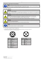
1. Check the supply voltage and voltage of the digital inputs.
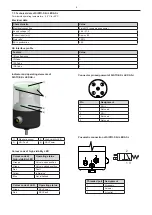
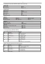
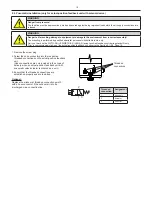
2. Gently connect the M12 socket to the M12 plug on the actual-position feedback unit and screw them firmly.
Ensure that the anti-rotation device is positioned correctly.
14
DANGER
Danger from electrical voltage!
The system must be de-energised and safeguarded against restarting and it must be verified that it is de-energised before it
is accessed. All applicable accident prevention, health and safety regulations must be observed when working on electrical
equipment.
WARNING
Danger to life resulting, damage to equipment or damage to the environment from incorrect assembly!
The mounting is performed by qualified specialist personnel with suitable tools, only.
Carry out work on the SISTO-SK-i LED/SISTO-SK-i LED AS-i actual-position feedback unit during standstill only.
Prior to commissioning/start-up of the actual-position feedback unit observe the Section 9.1-9.4, Page 16.
DANGER
Danger from electrostatic discharge!
Take special care when the housing is open due to possible electrostatic discharge.
NOTE
A shielded connection cable must be used for the installation.
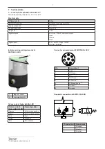
SISTO-SK-i LED
Pin
Assignment
1
+24 V
2
DO Open
5)
3
0 V
4
DO Closed
5)
5
DI Teach in
6)
6
DI Solenoid valve
6) 7)
7
DO Fault
5)
8
Not used
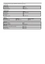
SISTO-SK-i LED AS-i
Pin
Assignment
1
AS-i +
2
Not used
3
AS-i -
4
Not used
5
Not used
_____________________________________________________
5)
Binary output
6)
Binary input
7)
With integrated solenoid valve only.


