16
9 Commissioning/Start-up/Shutdown/Removing
9.1 Commissioning the actual-position feedback unit SISTO-SK-i LED/SISTO-SK-i LED AS-i without an integrated
solenoid valve - on site
1. Verify that the electrical connections were established properly.
2. Check the supply voltage.
3. The valve actuator must be in its fail-safe position.
4. Check that the actual-position feedback unit is properly mounted on the valve actuator.
Start initialisation:
1. Keep the programming magnet in the middle of the top of the cover for at least 2 seconds. If the colour code start flashing yellow, remove
the magnet.
2. Activate the external solenoid valve to trigger the valve actuator.
3. The actual-position feedback unit automatically detects whether the actuator is opening or closing the valve when the valve is activated.
4. The valve actuator reaches the limit position.
5. Detection of the end position is indicated by the yellow colour code of LED.
6. Deactivate the external solenoid valve to move the actuator back to its fail-safe position.
7. Limit position will be saved and signalled via colour code of LED.
Actual-position feed back unit is ready to be operated.
9.2 Commissioning the actual-position feedback unit SISTO-SK-i LED/SISTO-SK-i LED AS-i without an integrated
solenoid valve - remote initialisation
1. Verify that the electrical connections were established properly.
2. Check the supply voltage.
3. The valve actuator must be in its fail-safe position.
4. Check that the actual-position feedback unit is properly mounted on the valve actuator.
SISTO-SK-i LED procedure:
1.
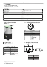
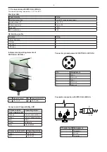
Start remote initialisation: Apply 24 volts to the teach-in input (pin 5) for at least 0.5 seconds.
2. Activate the external solenoid valve to trigger the valve actuator.
3. The actual-position feedback unit automatically detects whether the actuator is opening or closing the valve when the valve is activated.
4. The valve actuator reaches the limit position.
5. The actual-position feedback unit sends after three seconds a signal to pin 2 (DO Open) or pin 4 (DO Closed).
6. Deactivate the external solenoid valve to move the actuator back to its fail-safe position.
7. After three seconds a signal is sent to pin 2 (DO Open) or pin 4 (DO Closed).
8. The alternating voltage at the fault output (pin 7) is switched off.
(Table „Pin assignment“, Section 7.1, Page 7)
Actual-position feedback unit is ready to be operated.
SISTO-SK-i LED AS-i procedure:
1.
Start remote initialisation: Activate DO2 via AS-i master for at least 0.5 seconds.
2. The positioner is in the initialisation mode.
3. Activate the external solenoid valve to trigger the valve actuator.
4. The actual-position feedback unit automatically detects whether the actuator is opening or closing the valve when the valve is activated.
5. The valve actuator reaches the limit position.
6. The actual-position feedback unit sends after three seconds a signal to DI0 (Open) or DI1 (Closed).
7. Deactivate the external solenoid valve to move the actuator back to its fail-safe position.
8. After three seconds a signal is sent to DI0 (Open) or DI1 (Closed).
9. The alternating voltage at the fault output (DI3) is switched off.
(Table „Inputs and Outputs“, Section 7.5, Page 10)
Actual-position feedback unit is ready to be operated.

