background image

1 General

1.1 Principles

This operating manual describes the proper and safe use of the 


SISTO-SK-i LED intelligent actual-position feedback unit, or for the  
SISTO-SK-i LED AS-i intelligent actual-position feedback unit in all 
phases of operation.

The actual-position feedback unit SISTO-SK-i LED/SISTO-SK-i LED 
AS-i is used to measure the stroke of pneumatic valve actuators and 
to control them (optional).

In the event of damage, discrepancies and questions, immediately 
contact SISTO Armaturen sales organisation responsible in order to 
maintain the right to claim under warranty.

Only correct installation, maintenance or repair will ensure smooth 
operation of the actual-position feedback unit.

The manufacturer shall not accept any liability for the actual-position 
feedback unit if the manual set forth in this manual are not complied 
with.

In the case of any deviations or questions contact SISTO Armaturen.

1.2  Contact data

SISTO Armaturen S.A.
After-Sales-Services 
18, rue Martin Maas
L-6468 Echternach Luxembourg

Tel.: +352 32 50 85-1
Fax:  +352 32 89 56

Email: info@sisto-aseptic.com 
www.sisto-aseptic.com

1.3  Target group

This operating manual is aimed at the target group of trained and 

qualified specialist technical personnel.

1.4  Other applicable documents

Document

Description

Type series booklet 
8676.5 SISTO-SK-i LED

Description of the SISTO-SK-i LED/
SISTO-SK-i LED AS-i actual-position 
feedback unit

Operating manual 
0570.822

Installation/operating manual of the 
SISTO-C/SISTO-B diaphragm valves

1.5  Key to safety symbols/markings

Symbol

Description

DANGER

In conjunction with the signal word DANGER 
this symbol indicates a high-risk hazard, which 
if not avoided, will result in death or serious 
injury.

WARNING

In conjunction with the signal word WARNING 
this symbol indicates a medium-risk hazard, 
which if not avoided, could result in death or 
serious injury.

CAUTION

In conjunction with the signal word CAUTION 
this symbol indicates a low-risk hazard, which 
if not avoided, could result in minor injury.

Electrical hazard

In conjunction with one of the signal words this 
symbol indicates a hazard involving electrical 

voltage  and  identifies  information  about  pro

-

tection against electrical voltage.

4

Symbol

Description

CAUTION

In conjunction with the signal word CAUTION 
this symbol indicates a hazard for the machine 
and its functions.

NOTE

This symbol indicates recommendations and 
important information on how to handle the 
product.

2  Safety information

All the information contained in this section refers to hazardous situ-
ations. 
In addition to the present general safety information the action-related 
safety information given in the other sections must be observed.

2.1 General

This operating manual contains general installation, operating and 
maintenance instructions that must be observed to ensure safe product 
operation and prevent personal injury and damage to property.

Comply with all the safety instructions given in the individual sections 
of this operating manual.

The operating manual must be read and understood by the responsible 
specialist personnel/operators prior to installation and commissioning.

The contents of this operating manual must be available to the specialist 
personnel at the site at all times.

Information attached to the actual-position feedback unit, the valve 
or accessories must always be complied with and kept in a perfectly 
legible condition at all times.

This operating manual does not take into account:

•  Any eventualities or incidents which may occur during installation,


  operation and maintenance performed by the customer.

•  Local regulations; the operator must ensure that such regulations 


  are observed by all, including the personnel called in for installation.

The operating manual must be kept for the entire life cycle of the 
equipment.

For any queries you may have or in the case of damage, please contact 
SISTO Armaturen.

2.2  Intended use

▪  The  actual-position  feedback  unit  SISTO-SK-i  LED/SISTO-SK-i 


  LED AS-i is used to measure the stroke of pneumatic valve actua- 
  tors and to control them (optional).

▪  The actual-position feedback unit must only be operated in perfect 


  technical condition.

▪  Only operate the actual-position feedback unit within the operating 


  limits described in the other applicable documents.

▪  Other modes of operation, if not mentioned in the documentation, 


  must be coordinated with SISTO Armaturen.

2.2.1 Prevention of foreseeable misuse

▪  It is not allowed to enter following fluids in the air supply ports of the 


  actual-position feedback unit:

  - no liquids fluids
  - no fluids containing solids
  - no aggressive fluids
  - no combustible fluids.
▪  The actual-position feedback unit must not be operated in potentially 


  explosive atmospheres.


DANGER


Summary of Contents for SK-i LED

Page 1: ...Operating manual 8676 81 6 10 ORIGINAL SISTO SK i LED SISTO SK i LED AS i Intelligent Actual position Feedback Unit for Linear Valves Stroke 5 45 mm ...

Page 2: ...rs of the SISTO C LAP 12 8 2 Mounting of the actual position feedback unit on the valve actuators of the SISTO C LAP 520 530 13 8 3 Accessories 13 8 4 Mounting on valves from other manufactures 14 8 5 Electrical installation 14 8 6 Pneumatically installation only for actual position feedback unit with solenoid valve 15 9 Commisioning Start up Shutdown Removing 16 9 1 Commissioning the actual posit...

Page 3: ... pneumatic piston actua tor stainless steel SISTO C LAP 520 SISTO C diaphragm valve with pneumatic piston actua tor stainless steel SISTO C LAP 530 SISTO C diaphragm valve with pneumatic piston actua tor aluminium hard anodised SISTO SK i LED SISTO intelligent actual position feedback unit SISTO SK i LED AS i SISTO intelligent actual position feedback unit with AS Interface ...

Page 4: ...n with the signal word CAUTION this symbol indicates a hazard for the machine and its functions NOTE This symbol indicates recommendations and important information on how to handle the product 2 Safety information All the information contained in this section refers to hazardous situ ations In addition to the present general safety information the action related safety information given in the ot...

Page 5: ...t be eliminated For details refer to VDE regulations and the safety regulations laid down by the local energy supply companies for instance The operator has to ensure that the guards for live components are regularly checked for any damage The valve must never be ope rated without appropriate protection 2 6 Safety information for maintenance inspection and installation The operator ensures that ma...

Page 6: ...listed Metal inserts 1 4404 NBR sealing elements Cover PA6 Holder PA66GF30 Slide POM Bottom section PA66GF30 optional 1 4404 Socket PBT model LAP 520 PA Printed circuit board Elektronics Stroke sensor Elektronics Spring Stainless steel Connector M12 Elektronics Rod only for LAP 520 6 Exploded view ...

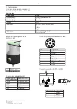
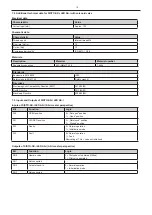
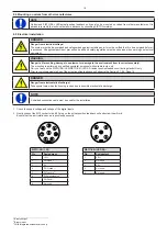
Page 7: ... Open Closed Fault Digital inputs 24 V Low 0 3 V High 18 24 V Remote initialisation Pin Assignment 1 24 V 2 DO Open 1 3 0 V 4 DO Closed 1 5 DI Teach in 2 6 DI Solenoid valve 2 3 7 DO Fault 1 8 Not used Threaded port Assignment 1 Air supply 2 Actuator 3 Air outlet 1 2 3 1 2 Indicator and operating elements of SISTO SK i LED Connector pin assignment of SISTO SK i LED Pneumatic connection of SISTO SK...

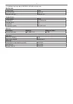
Page 8: ...acteristic Value Threaded port Internal thread M5 Flow rate lN min 15 P max bar 10 Compressed air quality ISO 8573 1 3 3 3 Standards Enclosure to EN 60529 IP65 Safety class to EN 61140 Safety class III Directives Electromagnetic Compatibility Directive EMC 2014 30 EU RoHS Directive 2011 65 EU Machinery Directive 2006 42 EG Description Material Material number Pneumatic connection X2CrNiMo17 12 2 1...

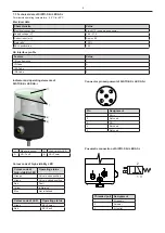
Page 9: ...ng elements of SISTO SK i LED AS i Connector pin assignment of SISTO SK i LED AS i Pin Assignment 1 AS i 2 Not used 3 AS i 4 Not used 5 Not used 1 Magnetic sensor 2 High visibility LED 3 AS i Fault 4 AS i Power Pneumatic connection of SISTO SK i LED AS i 1 2 3 Threaded port Assignment 1 Air supply 2 Actuator 3 Air outlet Colour code of high visibility LED Operating status Orange Valve in open posi...

Page 10: ...lass to EN 61140 Safety class III Directives Electromagnetic Compatibility Directive EMC 2014 30 EU RoHS Directive 2011 65 EU Machinery Directive 2006 42 EG Bit Function Logic DO0 Operate valve 0 Pilot valve not operated if fitted 1 Pilot valve operated DO1 Not connected DO2 Activate teach In 0 Normal operation 1 Initialisation mode DO3 Not connected Description Material Material number Pneumatic ...

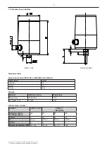
Page 11: ...ing variants available on request Actuator SISTO C LAP SISTO C LAP 520 530 Ordering code for mounting options 00 01 02 03 L mm 38 38 59 G G1 4 in M12 x 1 M18 x 1 M18 x 1 H mm 6 6 6 6 Diaphragm diameter MD 30 168 30 65 92 115 168 Material Material number Weight kg Plastic black PA66 GF30 0 170 X2CrNiMo17 12 2 1 4404 0 380 Dimensions mm Diameter 55 Height 87 Stroke 5 45 SISTO C LAP SISTO C LAP 520 ...

Page 12: ...o enter following fluids in the air supply ports of the actual position feedback unit no liquids fluids no fluids containing solids no aggressive fluids no combustible fluids ATTENTION Protect actual position feedback unit against source of radiation e g the sun Protect actual position feedback unit against vibrations NOTE If the actual position feedback unit is to be used in a damp environment st...

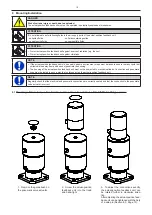
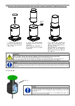
Page 13: ...es damage to equipment or damage to the environment due to incorrect assembly The assembling must be performed by qualified specialist personnel with suitable tools Carry out work on the SISTO SK i LED SISTO SK i LED AS i actual position feedback unit during standstill only Prior to commissioning start up of the actual position feedback unit observe the Section 9 1 9 4 Page 16 Adapter M18 x 1 NOTE...

Page 14: ...en working on electrical equipment WARNING Danger to life resulting damage to equipment or damage to the environment from incorrect assembly The mounting is performed by qualified specialist personnel with suitable tools only Carry out work on the SISTO SK i LED SISTO SK i LED AS i actual position feedback unit during standstill only Prior to commissioning start up of the actual position feedback ...

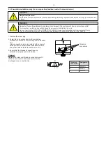
Page 15: ...nnector if the exhaust air is to be discharged via a connection line WARNING Danger from pressure The feed line must be depressurised bled and secured against being re pressurised before the air supply connections are released WARNING Danger to life resulting damage to equipment or damage to the environment from incorrect assembly The mounting is performed by qualified specialist personnel with su...

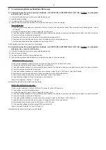
Page 16: ...erly mounted on the valve actuator SISTO SK i LED procedure 1 Start remote initialisation Apply 24 volts to the teach in input pin 5 for at least 0 5 seconds 2 Activate the external solenoid valve to trigger the valve actuator 3 The actual position feedback unit automatically detects whether the actuator is opening or closing the valve when the valve is activated 4 The valve actuator reaches the l...

Page 17: ...l is present at pin 2 DO Open or pin 4 DO Closed 4 No voltage is present at pin 7 DO Fault Table Pin assignment Section 7 1 Page 7 Actual position feedback unit is ready to be operated SISTO SK i LED AS i procedure 1 Start remote initialisation Activate DO2 via AS i master for at least 0 5 seconds 2 The actual position feedback unit actuates the internal solenoid valve reaches the both limit posit...

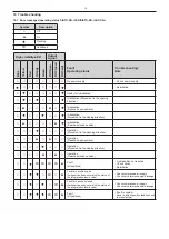
Page 18: ...ion Movement in the opening direction Operation Reached open position Operation Movement in the closing direction Operation Reached closed position Fault all positions Limit position not reached Check stroke Reinitialise Fault limit position open limit position does not match the status of the integrated solenoid valve Check compressed air supply Check valve for mechanical blockage Fault limit pos...

Page 19: ...t possible Peripheral fault Signal of peripheral fault generated at FID input Worse Peripheral fault with reset Data Strobe driven LOW for more than 44µs 19 Symbol Description Off On Flashing Operating status Colour code of LED AS i Power Green AS i Fault Red 11 Maintenance Cleaning The SISTO SK i LED SISTO SK i LED AS i actual position feedback unit was designed to be maintenance free However che...

Page 20: ...trieb genommen werden wenn die Maschine in die sie eingebaut wird die Anforderungen der Richtlinie 2006 42 EG erfüllt Machinery Directive 2006 42 EC Declaration of incorporation according to annexe IIB Manufacturer address SISTO Armaturen S A 18 rue Martin Maas L 6468 Echternach Luxembourg Description of the partly completed machinery Actual position feedback unit type SK i LED or actual position ...

Page 21: ... 2011 65 EU Beschränkung der Verwendung bestimmter gefährlicher Stoffe in Elektrogeräten und Elektronikgeräten RoHS 2014 30 EU Elektromagnetische Verträglichkeit Herewith we SISTO Armaturen S A 18 rue Martin Maas L 6468 Echternach Luxembourg declare that the listed products Actual position feedback unit type SISTO SK I LED Actual position feedback unit type SISTO SK i LED AS i intended to be used ...

Page 22: ...t to technical modification without prior notice 8676 81 6 10 10 11 2020 SISTO Armaturen S A 18 rue Martin Maas 6468 Echternach Luxembourg Tel 352 32 50 85 1 Fax 352 32 89 56 e mail sisto ksb com www sisto lu ...

Reviews: