background image

Construction

0---14

CONSTRUCTION

General

The Sisudiesel 20/34---series engines (3---, 4---, or 6---cylin-

ders) are water---cooled, four stroke, direct---injection in---line

diesel engines. All engines are produced as naturally aspir-

ated engines, turbocharged engines and the four--- and six

cylinder engines also as intercooled.

The engines have a rigid and ribbed cylinder block. The crank

mechanism is designed for supercharging. The cylinder

liners are wet and supported at the middle. The cylinder head

bolts are high tensile bolts.

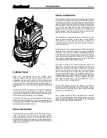
Cylinder block

The cylinder block is the main body of the engine, to which

other engine parts are attached. Wet and replaceable cylinder

liners are supported at the middle which reduces vibrations

and directs coolant circulation mainly to the upper part of the

liners.

The seal between the cylinder liner lower part and the cylinder

block is achieved by three o---rings, which are fitted in grooves

in the liner. The upper part is sealed by the cylinder head

gasket.

The camshaft is located in the cylinder block. The camshaft

front bearing location is fitted with a separate bearing sleeve.

The remaining bearing locations are machined directly in the

cylinder block. The latest 620/634---engines have separate

bearing sleeves in all camshaft bearing locations. The drilling

for the camshaft rear end is covered with a plug.

There are spaces on both sides of the rear main bearing for

guide bearing shims (the crankshaft thrust bearings).

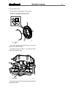
Flywheel housing

The flywheel housing is fitted at the rear end of the cylinder

block. The seal for the crankshaft rear end is placed in a bore

in the housing. The starter motor fixing point is fitted in the fly-

wheel housing.

The lower face of the flywheel housing functions as a sealing

surface for the oil sump gasket. This means that the lower face

of the cylinder block must be level with the flywheel housing.

When fitting the flywheel housing, its position is determined

by tension pins.

The flywheel housing are delivered according to the require-

ments set, by the engine application and differet flywheel

housings can be mounted on all engine types.

20--- 7

Summary of Contents for 320

Page 1: ...WORKSHOP MANUAL SISUDIESEL 320 420 620 8366 40634 634 ...

Page 2: ...Inc FIN 37240 Nokia Finland Telephone 358 3 341 7111 E mail info sisudiesel sisudiesel com www sisudiesel com Diesel Engines After Sales Telefax 358 3 341 7333 Sisu Diesel Inc takes no responsibility for any damages caused because of incorrect information in this manual ...

Page 3: ...14 Cylinder block 0 14 Flywheel housing 0 14 Cylinder head 0 15 Valve mechanism 0 15 Crank mechanism 0 15 Timing gears 0 16 Lubricating system 0 17 Cooling system 0 18 Inlet and exhaust system 0 19 Electronic Engine Management system EEM 0 20 WORK INSTRUCTIONS 1 CYLINDER BLOCK A Measuring cylinder liner wear 1 1 B Removing cylinder liner 1 1 C Checking cylinder block 1 1 D Changing camshaft bushin...

Page 4: ...ing gear casing 9 1 B Reconditioning idler gear 9 1 C Fitting timing gear casing 9 2 D Idler gear with bevelled ball bearings 9 4 E Power take off 9 5 10 LUBRICATION SYSTEM A Reconditioning of oil relief valve for lubricatin oil pressure 10 1 B Removing and dismantling lubricating oil pump 10 1 C Assembling and fitting lubricating oil pump 10 2 D Fitting oil sump gasket 10 3 E Lubricating oil cool...

Page 5: ... 13 18 STANADYNE DISTRIBUTOR PUMP Technical data 13 19 A Removing pump 13 24 B Fitting injection pump and adjusting injection timing 13 24 C Bleeding fuel system 13 25 D Fuel feed pump 13 25 E Injectors 13 25 F Adjusting low idling speed 13 26 G Bleeding Thermostart system 13 26 H Wiring diagram of electrical advance CCA 13 26 I Checking injection timing dynamic 13 27 Fuel quality requirement 13 2...

Page 6: ...perature of the parts is 20 C unless other wise stated Before starting the repair work read the safety instructions in the beginning of this book Make sure that you have all necessary tools parts and accessories at your disposal The special tools mentioned in the work instructions are not all essential but they speed up and facilitate the work and contribute to successful execution of work An engi...

Page 7: ... noise injuries Stop the engine always before service or repair work Avoid touching the exhaust manifold turbocharger and the other hot parts of the engine Open the radiator cap with care when the engine is hot as the cooling system is pressurised The cooling liquid and lubrication oil of a hot engine causes injuries when touching the skin Open fire smoking and sparks should not be allowed near th...

Page 8: ...g order 1 2 3 1 2 4 3 1 5 3 6 2 4 Compression pressure bar1 24 Weight kg2 275 280 335 340 340 345 500 510 515 Direction of rotation from the engine front clockwise 1 Minimum value at operating temperature and starting revs Max permitted difference between cylinders 3 0 bar 2 Without flywheel and electrical equipment LIFTING THE ENGINE Safe lifting of the engine is done with a lifting device where ...

Page 9: ...ve 20 9101 66000 Milling tool for injector seat 21 9052 46660 Drift for 36 mm cup plug 22 9101 65800 Drift for removing valve guide 23 9101 65900 Drift for fitting valve guide 24 9024 55800 Spanner for crankshaft nut 634 engines 620 MF Steyr tractors 25 9101 65700 Spanner for crankshaft nut 26 9052 48800 Puller for crankshaft gears 27 9020 01100 Conical sleeve for fitting pistons 28 9052 46900 Pis...

Page 10: ...Special Tools 0 5 1 2 3 4 6 7 8 9 10 5 11 12 13 14 15 16 17 18 19 21 22 23 24 25 26 29 27 30 31 20 28 32 33 37 40 41 42 39 38 34 35 36 20 6 ...

Page 11: ...inder liner flange 131 700 131 800 mm Cylinder head Height of cylinder head 104 800 105 000 mm Height of cylinder head after repair grinding minimum 104 000 mm Inside diameter of valve guide not fitted 9 000 9 015 mm Outside diameter of valve guide 16 028 16 039 mm Diameter of valve guide bore in cylinder head 16 000 16 018 mm Position of valve guide top above cylinder head surface 21 mm Depth of ...

Page 12: ...epth of valve face below cylinder head surface inlet valve 0 7 0 05 mm max 2 20 mm exhaust valve 0 6 0 05 mm max 2 20 mm Valve spring free length 69 8 mm Spring pressure when spring compressed to a length of 48 6 mm 327 17 N 37 4 mm 500 23 N Rocker arm shaft diameter 19 959 19 980 Inside diameter of rocker arm bearing bush when fitted in position 19 990 20 010 mm Outside diameter of rocker arm bea...

Page 13: ...025 mm Main bearing shell thickness standard 2 955 2 965 mm 1st undersize 0 25 mm 3 080 3 090 mm 2nd undersize 0 50 mm 3 205 3 215 mm 3rd undersize 1 00 mm 3 455 3 465 mm 4th undersize 1 50 mm 3 705 3 715 mm bearing 8361 40950 see page 5 1 instruction B 3 705 3 715 mm Main bearing clearance 0 050 0 127 mm Length of thrust bearing journal journal nearest to flywheel standard 2 standard thrust plate...

Page 14: ...th against camshaft gear mark 1 dot on tooth against fuel injection pump gear mark 1 dot on notch On camshaft gear 1 dot on notch On injection pump gear 1 dot on tooth Connecting rod Inside diameter of piston pin bush with bush pressed into connecting rod 40 025 40 040 mm Outside diameter of piston pin bush 44 080 44 120 mm Outside diameter of piston pin bush oversize 8353 28326 44 580 44 620 mm I...

Page 15: ... ring 1 5 mm Max permissible weight difference between pistons in same engine 25 g Piston to be heated up to 100 C before fitting gudgeon pin Piston position in cylinder combustion chamber of piston to face towards injector Lubricating system Oil pressure at normal running temperature at idling speed min 100 kPa 1 0 kp cm2 at running speed 250 400 kPa 2 5 4 0 kp cm2 Free length of oil pressure val...

Page 16: ...50 mm Housing diameter 634 engines 620 engines J 7891 56 000 56 120 mm Thickness of gears 32 000 32 027 mm End play of gears 0 03 0 11 mm Depth of housing 32 000 32 043 mm Number of teeth on drive gears 46 pcs Coolant pump 320 420 engines Outside diameter of bearing 38 087 38 100 mm Inside diameter of bearing housing in pump body 38 058 38 083 mm Shaft diameter 15 910 15 920 mm Impeller hole diame...

Page 17: ...009 mm Thermostat Spare part number Type Opening Fully Max stroke begins at open at mm 8361 15646 ø67 79 C 79 2 C 94 C 8 8361 15718 ø67 83 C 83 2 C 97 C 8 8366 59685 ø67 86 C 86 2 C 99 C 8 8360 15156 ø54 79 C 79 2 C 94 C 7 5 8363 31590 ø67 83 C 83 2 C 95 C 8 Turbocharger Schwitzer S1A 320 DS Shaft end float max 0 14 mm Shaft radial clearance 1 max 0 61 mm Turbine housing attaching bolts 22 Nm Nut ...

Page 18: ...Piston cooling valve 620 634 30 Oil pump gear nut 60 Oil pump retaining screws 60 Oil cooler connecting piece 60 Coolant pump pulley nut 120 Fan bolts 30 Exhaust manifold bolts 50 Intake manifold bolts 30 Injection pump pressure valve holder 45 Injection pump gear retaining nut 90 Injection pump gear retaining nut Bosch P 200 Injector attaching nuts on studs 15 Injector nozzle sleeve 60 Compressor...

Page 19: ...e cylinder head gasket The camshaft is located in the cylinder block The camshaft front bearing location is fitted with a separate bearing sleeve The remaining bearing locations are machined directly in the cylinder block The latest 620 634 engines have separate bearing sleeves in all camshaft bearing locations The drilling for the camshaft rear end is covered with a plug There are spaces on both ...

Page 20: ...f the V belt pulley An oil deflector ring is fitted between the hub and gear wheel and a dust shield is fitted on the hub in order to protect the seal The crankshaft is supported on the cylinder block by main bearings which are placed on both sides of each cylinder Thus there is one main bearing more than cylinders The crankshaft thrust washers are placed in both sides of the rear most main bearin...

Page 21: ...d tothe front of the engine The timing gear drives the camshaft fuel injection pump and oil pump If the engine is equipped with a hydraulic pump it is driven via a gear or a separate drive unit The idler gear is supported with a bearing sleeve ball bearing 620 634 on the shaft on the front face of the cylinder block Two different dimensions of gear and shaft is used ...

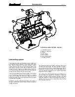
Page 22: ...lery In 620 634 engines with high power rating is the bottom of the piston cooled with oil spray always when the oil pressure is higher than 3 bar Lubricating system 620 634 engines 1 Lubricating oil pump 2 Pressure relief valve 3 Oil filter 4 Turbocharger 5 Main oil gallery 6 Piston cooling nozzle 7 Oil pressure sensor The oil pressure relief valve is located under the oil filter on the left hand...

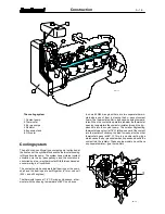
Page 23: ... engines The thermostat opens at 79 C During a cold season a ther mostat with the opening temperature of 83 C can be use In some 620 634 engines there are two separate thermo stats where one of them is steering the by pass of coolant liquid The thermostats differ in types and opening tempera tures When the coolant temperature is below the thermostat opening temperature the coolant circulates throu...

Page 24: ...ith high tensile bolts without a separate gasket Retightening of the manifold bolts is unnecessary In the marine and generator engines a liquid cooledexhaust manifold is used that is connected to the engines cooling liquid circulation so called freshwater circulation These exhaust manifolds are sealed from the liquid circulation part with o rings in 420 engines and with level seals in 320 620 634 ...

Page 25: ...tem significantly im proves the properties of the engine and adds several func tions and operational features that could not be realised with mechanical governors The EEM system is applicable to all kinds of vehicles on or off road The system consists of the following components Fuel injection pump with electrical actuator system Electronic control unit Sensors for engine parameters and speed dema...

Page 26: ...ng cylinder liner puller 9051 73100 9051 73100 21 2 C Checking cylinder block 1 Clean the cylinder block and all oil ways 2 Check the cooling channels and remove the scale andsedi ment to ensure engine cooling 3 Check the tightness of the cup plugs and threaded plugs in the cylinder block as well as the condition of the cylinder block and sealing faces 4 Measure the wear of the camshaft bearing po...

Page 27: ...her camshaft bear ings which do not normally have bushings Part numbers and machining dimensions for the bushing locations are shown in the figure Observe the position of the bushing oil holes It is unnecess ary to ream the bushings after fitting Note From engine number L 13188 the cam shaft front end bushing is equipped with the oil groove on the outside the groove was earlier on the cam shaft As...

Page 28: ... plate 8361 24210 in those engines where the flywheel housing is not covering the blocking plug Order no Hole diameter 1 8363 24661 56 02 56 05 2 8368 52460 55 42 55 45 3 8368 52460 55 42 55 45 4 8368 52461 55 64 55 67 Order no Hole diameter 1 8363 24661 56 02 56 05 2 8368 52466 55 62 55 65 3 8368 52460 55 42 55 45 4 8368 52466 55 62 55 65 5 8368 52467 55 84 55 87 F Fitting plug at camshaft rear e...

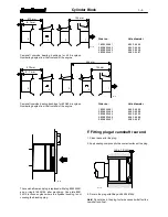
Page 29: ...ole contact surface 3 If the recess is damaged or the cylinder liner height see point 5 needs to be adjusted use milling cutter 9101 65600 If necessary a light lapping can be executed after milling with the help of the cylinder liner Apply lapping paste to the under side of the cylinder liner flange and twist the liner with twisting tool Lapping is not suitable for adjusting the cylinder liner hei...

Page 30: ...adjusted with a cylinder liner recess cutter 9101 65600 7 If the liner height of acylinder lineris notthe sameall theway round the cylinder liner flange and the cylinder block recess depth should be checked Cylinder liners with warped flanges should be discarded 21 15 Musta Black Svart Schwarz Vihreä Green Grön Grün 8 Fit the o rings into the grooves in the cylinder lower part and lubricate them w...

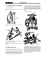
Page 31: ...2 9 and outer ring hexagonal bolts to 110 Nm 8 8 150 Nm 12 9 NOTE MODIFICATION OF THE FLYWHEEL HOUSING All the below mentioned flywheel housings have been in the inner circle added with 3pcs Æ11 mm holes E and in in the outer circle with 1 pcs Æ13 mm hole A Under the bolts in the added holes has to be added a spring washer Æ10 mm order no 5009 51000 3 pcs E and Æ12 mm order no 5009 51200 1 pc A Th...

Page 32: ... DRY NOT OILED T O 22 4 O Sleeve T Seal Put the sleeve against the crankshaft rear end so that the sleeve is on the shaft bevelling Push the seal over the sleeve on the shaft and further against the flywheel housing 9052 46300 22 5 Remove the sleeve and hit the seal into position with the fit ting tool 9052 46300 ...

Page 33: ...ead B Removing valves Ensure that valves which are to be re used are marked so that they are fitted in their original locations 9052 47200 23 1 9101 66200 1 Install the counter screw 9052 47200 for the valve spring in stalling tool in the rocker arm cover bolt On the 320 and 620 634 engines there is not a screw stud at the valves for the centre cylinder A bolt of suitable length should be used ins...

Page 34: ... drift 9101 65800 Clean the valve guide locations 2 Lubricate the outside of the new guides and fit them using drift 9101 65900 which ensures the correct fitting height 21 mm over the spring face 9101 65900 23 6 23 7 3 The guides are the same for the inlet and exhaust valves Ensure that the steepest chamfer on the guide faces the valve head Check that the valves do not bind in the guides E Machini...

Page 35: ...ines when repairing seat ring no 8368 55347 See technical data point cylinder head G Grinding valves In order toensure that there is a proper seal around the valves there is a difference in the sealing surface angles Thus there is a very narrow sealing surface which seals effectively even after prolonged running 23 10 A B C A B C Inlet 35 20 35 20 0 7 0 05 mm max 2 20 mm Exhaust 45 20 45 20 0 6 0 ...

Page 36: ...anifold can damage if the heads are not parallel Clean and lubricate and fit the bolts 420 1 2 3 4 5 6 7 8 9 10 11 12 13 14 15 16 17 320 620 634 1 2 3 4 5 6 7 8 9 10 11 12 13 14 15 16 17 18 19 20 21 22 23 13 23 12 4 Pictures above show the correct tightening order of the cyl inder head bolts The order has also been marked on the cyl inder heads 5 Tighten the cylinder head bolts progressively as fo...

Page 37: ... of the rocker arm shaft Lubri cate the shaft and fit various parts in a correct order Note the correct position of the shaft and the bearingbrackets Thesplit side of the bracket and the shaft oil holes must be turned to the valve side see figure above Fit the other end plug NOTE ENGINES FROM 96 WEEK 34 From the above mentioned date a new valve mechanism push rods and rocker cover fastening taken ...

Page 38: ...s which are to be refitted 9 Fit the key in its groove Heat the camshaft gear to 200 C in an oven and fit it on the shaft 10 Lubricate bearing surfaces and lobes and insert the shaft in the cylinder block Ensure that the aligning marks on the gears agree 11 Fit the timing gear casing cover and the crankshaft V belt pulley and hub 12 Free the pushrods and fit the rocker arm mechanism Ad just the va...

Page 39: ... is completely open valve no 6 Check valves in the 2nd cylinder when the exhaust valve of no 1 cylinder is completely open valve no 2 Check valves in the 3rd cylinder when the exhaust valve of no 2 cylinder is completely open valve no 4 420 engines Rotate the crankshaft in the running direction until the valves in the 4th cylinder are rocking exhaust closes inlet opens Check the valve clearance of...

Page 40: ...en zeroed to the dimensions obtained in point 2 With this method the indicator shows the actual bearing clear ance Measure in several points in case the worn bearing housing is not round 25 2 4 If the bearing clearance exceeds 0 18 mm for main bear ings or 0 14 mm for connecting rod big end bearings with new bearing shells the bearing journals on the crankshaft should be ground Refer to the specif...

Page 41: ...ring with no hole B to the bearing cap Ensure that the bearing shell clamping claws fit into their notches and that the shells to be fitted in the cylinder block have a hole coinciding with the oil port 3 Lubricate the bearing surfaces and fit the crankshaft Fit the crankshaft thrust bearings with the lubricating grooves facing the crankshaft 200 Nm 25 6 4 Fit the main bearing caps according to th...

Page 42: ...ts do not have injection timing mark Make the marking on the new damper in connection with installation 4 Rotate the crankshaft until the piston of the 1st cylinder re aches its top dead centre Drop cyl no 1 inlet valve down against the piston head Set the dial gauge on top of the valve stem end and zeroit at the piston top dead centre Then rotate the crankshaft opposite to running direction until...

Page 43: ...ration damper should be replaced every 4000 running hours I Viscose type vibration damper 1 Housing 2 Damper mass 3 Liquid cavity 4 Bushing In the 634 engines and some 620 engine versions there is a vibration damper of so called viscose type Inside the damper there is a housing filled with stiff silicone oil in where the damping substance is situated with very small tolerances Note Even a small de...

Page 44: ...le in the connecting rod After fitting drill Æ 5 mm oil hole and ream the bush to at tain its correct diameter Note The connecting rod can if needed be fitted with a 0 5 mm oversize bushing 8353 28326 See technical data point connecting rod Big end bearing 1 Fit the bearing shells together and tighten the screws 2 Measure the I D using a cylinder gauge which has been zeroed to the diameter of the ...

Page 45: ...230 2249 g E 8366 52108 2250 2269 g H 8366 52109 2270 2289 g I 8366 52110 2290 2309 g J 8366 52111 2310 2329 g K 8366 52112 2330 2349 g L 8366 52113 2350 2369 g M 8366 52114 2370 2389 g N 8366 52115 2390 2409 g O 8366 52116 2410 2429 g P 8366 52117 2430 2449 g R 8366 52118 2450 2469 g S 8366 52119 2470 2489 g T 8366 52120 2490 2509 g U 8366 52121 2510 2529 g New connecting rod from engine number L...

Page 46: ...n ring gap by pushing one piston ring at a time into the cylinder bore The piston ring gap must not ex ceed 1 mm on 1 and 3 piston rings and 1 5 mm on 2 piston ring 4 Fit the piston rings on the piston using the piston ring pliers Ensure that the rings are fitted in the correct groove and that TOP or the manufacturer s designation faces upwards 26 11 E Checking pistons Check the condition of the p...

Page 47: ...e bearing locations are clean and place the bearing shells in the connecting rod and bearing cap Note the position of the bearing shells 2 Lubricate piston rings and cylinder bore Ensure that the piston ring gaps are spread around the piston 26 14 9020 01100 3 Use a piston ring strap or preferably a fitting tool Fit the pis ton with the marking on the connecting rod weight class facing the camshaf...

Page 48: ...gs should be reamed to a correct dimension see Specifications 27 1 1 Synchronisation marking notch 2 Marking against crankshaft punch mark 3 Place the weights in the body observing the notch mark ings The gear wheel with the punch mark runs against the crankshaft and should therefore be placed highest Insert the shafts remembering the thrust bearings Apply thread lock fluid Loctite 270 to the lock...

Page 49: ... the flywheel to the crankshaft rear end As a guide pins can be used studs M12 2 pcs which are screwed in to the flywheel fixing bolt holes The position of the flywheel is free in engines where the injection timing is marked on the crankshaft front end In some engine versions one of the re taining screws have been replaced by a guide pin to deter mine the crankshaft position 3 Tighten the flywheel...

Page 50: ...l deflector ring at the front end of the crankshaft 6 Remove the injection pump Note If the timing gear casing is not to be changed the injec tion pump can remain in place In which case disconnect all leads and pipes from the pump 7 Unscrew the idler gear bolts 17 and 22 mm Remove the flange gear wheel and bearing journal 8 Extract the camshaft Note If the cylinder head and valve mechanism have no...

Page 51: ...ins already machined 1 Fit the casing with a new gasket against the cylinder block Drive in the tension pins with drift 9025 98700 Tighten bolts and nuts 2 Fit the injection pump together with gear wheel if re moved 3 Lubricate the camshaft bearings and insert the shaft in the cylinder block Release the pushrods and tappets if they have been suspended 29 4 4 Fit the idler gear with shaft stud and ...

Page 52: ...Fit the protective plate into the seal location and fit the crankshaft front seal with special tool 9030 15200 9025 98900 29 8 8 Fit the dust shield on the crankshaft V belt pulley hub if it has been removed Use drift 9025 98900 600 Nm 320 420 29 9 1000 Nm 620 634 9 Lubricate both the seal and sealing surfaces and fit the crankshaft V belt pulley with hub 10 Lubricate the crankshaft nut threads Ti...

Page 53: ...from the inner ring The idler gear screw tight ness is 180 Nm 1 Camshaft gear 2 Idler gear 3 Injection pump gear 4 Hydraulic pump gear 5 Crankshaft gears 6 Oil pump gear 7 Idler gear of compressor 8 Compressor gear 30 Nm 29 12 2 If the compressor gear shaft has been removed apply on its outer face Loctite 601 and hit the shaft in its position so that the shaft and gear housing back surfaces are at...

Page 54: ...c pump 29 14 Note when assembling the P T O the front bearing seal posi tion Use molybdenite sulphide MoS2 ball bearing grease NLGI 2 for the grooves of the hydraulic pump shaft and the coupling sleeve Note Some P T O are equipped with on outer lubricating possibility pipe In this case the front bearing is not sealed like in picture This P T O is known from the M6x1 thread in the cover ...

Page 55: ...downwards Note From engine no J 7595 engines without oil cooled piston From engine no J 14016 engines with oil cooled piston The engines are equipped with a new type of oil pressure valve In the construction of the new valve the hydraulic vibra tions are damped it is more reliable and it gives the best opti mised pressure level 210 1 1 Loctite 638 B Removing and dismantling lubri cating oil pump 1...

Page 56: ...artly tighten the bolts Rotate the pump shaft and tap the side of thecover lightlyuntil theposition isreached where the shaft rotates most freely Tighten the bolts and check that the shaft still rotates freely 2 Fit the key and drive gear onto the shaft tapered joint with out key on the later pumps Apply Loctite 242 onto the nut threads and tighten the nut to 60 Nm Remember the washer under the nu...

Page 57: ...nect coolant pipes in the correct way 3 Apply locking fluid to the nipple the thread which attaches to the filter head and tighten it to a torque of 60 Nm F Piston cooling nozzles 620 634 The cooling nozzles can be removed after removing the oil sump The nozzles have a ball valve with an opening pressure of 3 0 25 bar 210 9 1 Change the valve if necessary Detach the valve from the engine and remov...

Page 58: ... 40 10W 30 10W 40 15W 40 20W 20 20W 40 30 40 40 Lubrication System 10 4 G Lubricating oil quality requirements Naturally aspirated and turbocharged engines API CF 4 CG 4 CH 4 ACEA E2 E3 96 E4 98 E5 99 Low emission E engines API CG 4 CH 4 ACEA E3 96 E4 98 E5 99 ...

Page 59: ...eparate winter thermostats Note Modification of the by pass pipe 320 420 engines from engine number D 3056 620 engines from engine number D 3532 211 3 The rubber seal ring between the coolant pump and the ther mostat housing has been modified to two o ring seals At the same time also the by pass pipe is modified The new parts can during a repair be installed instead of the earlier used B Reconditi...

Page 60: ...ed Both these seals are fitted with their own drift see figure above 1 8 2 2 mm 178 5 mm 320 174 5 mm 320 E 7536 420 E 7055 211 7 420 9 Press the impeller and the hub to the correct depth see fig ure and support the shaft at the other end Ensure that the shaft can rotate freely Fit the rear plate using a new gasket C Reconditioning coolant pump Separate ball bearings 320 420 620 634 1 Drain the co...

Page 61: ...e same time sup porting the shaft at the other end The mounting depth of the impeller is in 320 420 engines 1 8 2 2 mm and in 620 634 engines 0 8 1 2 mm see figure above Make sure that the shaft can rotate freely 10 Fit the belt pulley and tighten its attaching nut to a torque of 120 Nm 211 10 11 Fit the rear plate using new seals Use in 620 634 en gines guide pins ø8 5 mm in the holes shown with ...

Page 62: ...ity requirements of coolant The coolant used must meet the standards ASTM D 3306 or BS 6580 1992 Mixing proportion should be 40 60 of ethylene propy lene glycol based coolant and the rest water The best ratio is 50 50 In warm climates the 30 mixture ratio gives enough good protection against corrosion Water used should be clean and soft water i e that it does not include metals and their salts Che...

Page 63: ...ine or renew the intake manifold On 620 634 engines ensure that the cylinder heads are par allel 3 Fit a new gasket and fasten the intake manifold Tighten the manifold fixing screws to a torque of 30 Nm Fasten the air pipes carefully 4 Check that the exhaust manifold is air tight Tighten the nuts bolts to 50 Nm and inspect for any damage cracks de formation corrosion etc Check also the connection ...

Page 64: ...ion The setting of the injection pump critically affects the function of the turbocharger The injection pump should be adjusted according to the manufacturers instructions 1 Check the tightness of the intake and exhaust manifolds and that they are securely fastened Ensure that there are no loose carbon or rust particles or other foreign objects in the manifolds 2 Connect the turbocharger to the ex...

Page 65: ...tion of rotation clockwise Diameter of pump piston Bosch A 9 5 mm Bosch P 12 mm Stroke Bosch A 8 mm Bosch P 11 mm Injection advance see injection pump adjusting values Oil fillings 1 320 0 3 l 420 0 4 l 620 634 0 6 l 1 When fitting fuel injection pump Fuel feed pump Type 320 Bosch FP KSG 24 AD 207 420 620 634 Bosch FP KEG 24 AD 504 Construction piston pump separate hand pump Fuel feed pressure ove...

Page 66: ... tank 2 Prefilter 3 Fuel feed pump 4 Fuel filter 5 Fuel injection pump 6 Injector 7a Thermostart fuel reservoir 7b Magnetic valve 8 Glow plug 9 Overflow valve Symptoms of dirty or faulty injectors are Knocking is an indication that one of the injectors is faulty When a cold engine ticks over a certain amount of knocking is unavoidable If the engine knocks after it has reached normal operating temp...

Page 67: ...t end of the injection pump In some versions specially locally installed engines the return of the oil is lead through a hose from the regulator cover to the crankcase The fuel feed pressure which fills the high pressure pump el ements with fuel is created by a piston pump which is at tached to the side of the fuel injection pump The piston pump is driven from an eccentric on the camshaft of the i...

Page 68: ...pprox 8 This should be borne in mind when checking the fuel in jection timing This groove improves the cold starting prop erties of the engine It works fully automatically When the en gine has stopped the control rod in the injection pump turns the plungers so that the starting groove faces towards the re lease passage When the engine has started and when the in jection pump has reached a certain ...

Page 69: ...hts The position of the governor control and of the gov ernor weights is transferred through the governor lever link age to the control rod The governor has one governor spring Starter spring which is attached to the upper end of the con trol lever it pulls the control rod to the starting position when the engine stops This means that the amount of fuel injected when the engine is started automati...

Page 70: ... pipe when the pipe or reservoir has been emptied during repair work etc This prevents damages tothe glow plug caused by lack of fuel dur ing starting System with the magnetic valve 213 11 1 Disconnect the electrical wire from the glow plug and the fuel pipe 2 Connect electricity to the magnetic valve and rotate the en gine until fuel comes out from the fuel pipe connection 3 Tighten the pipe conn...

Page 71: ...e gauge at the moment the valve opens with the prescribed value 0 6 1 0 bar 3 If the recorded opening pressure deviates from the pre scribed value the overflow valve should be changed Note If the recorded pressure is considerably lower than the prescribed value there may be a fault in the hand pump or the fuel feed pump valves E Changing fuel feed pump valves 1 Clean the feed pump Disconnect fuel ...

Page 72: ...pis ton reaches its compression stroke top deadcentre Thenturn the crankshaft backwards until the timing mark on the pulley flywheel passes the timing indicator 9025 99000 213 17 5 Remove the protecting cap for the control rod on the injec tion pump front face Fit adjusting tool sleeve for limiting con trol rod travel 9025 99000 The tool moves the control rod to the running position 6 Disconnect t...

Page 73: ...t turnthe indicatorpin sothat the groove points outwards running position and push the pin into the hole Refit the plug Usage of the electrical inspection device Bosch KDEP 1601 0 986 612 174 Also in electrical device can be used to check the timing 1 Turn the crankshaft to a position where the 1st cylinder pis ton reaches its compression stroke top deadcentre Thenturn the crankshaft backwards unt...

Page 74: ...uel injection pump Bosch A injection pump 1 Check the condition of the o ring between the pump and the timing gear casing Change the o ring if necessary 213 21 2 Lubricate the o ring and place the injection pump so that the key on the pump shaft aligns with the key slot inside the gear Tighten the pump attaching nuts Note The injection pump with adjusting indicator in the cov ernor housing don t h...

Page 75: ...o a position where the 1st cylinder pis ton reaches its compression stroke top deadcentre Thenturn the crankshaft backwards until the mark on the pulley passes the timing indicator After that rotate the crankshaft slowly to running direction until the mark on the pulley is at the point of the timing indicator or the timing mark on the flywheel is at the point of locator 9025 99100 see instruction ...

Page 76: ...lean fuel or test liquid and at the same time rotate the plunger in its guide and press the sealing surfaces against each other 213 25 7 Fit the pressure valve into the fuel injection pump Place the spring in place and tighten the holder Note Replace the sealing ring and o ring 8 Tighten the holder as follows Tighten first to 30 Nm Open the holder about a turn and tighten to 40 Nm Open the holder ...

Page 77: ...mist is dangerous to inhale 1 Clean the injector with cleaning fluid and a soft brush The carbon deposits must not be knocked off or removed in any other way which may damage the nozzle 213 29 2 Secure the injector in a test bench and check the follow ing injector opening pressure the properties of the chattering creaking sound and the form of the spray pattern sealing of nozzle valve against its ...

Page 78: ...crew the nozzle cap nut Remove the nozzle and the parts inside the holder 3 Clean the nozzle in cleaning fluid both inside and outside 4 Clean the nozzle holes with a needle including in cleaning set 8360 83288 5 Test the movement of the nozzle valve as follows 213 30 Rinse the parts thoroughly in fuel or testing fluid Pull the valve out of the nozzle body to 1 3 of its length If the fit is correc...

Page 79: ... the attaching clamp and tighten the nuts evenly to 15 Nm 4 Connect the leak off line together with new sealing washers and connect the delivery pipes Note The screw studs in the cylinder head for the injectors should only be finger tight If tools have to be used the studs should be tightened only lightly Note Make sure that the injector is of a correct type Wrong injectors cause malfunctions and ...

Page 80: ...stallation marks of injection pump 2 Overflow flange 3 Throttle lever 4 Stop lever 5 Stop solenoid 6 Identification plate TECHNICAL DATA Injection pump CAV Type DPA Injection order 420 1 2 4 3 620 1 5 3 6 2 4 Direction of rotation clockwise Injection advance see pump installation marks Fuel feed pump Construction diaphragm pump separate hand lever Fuel feeding pressure static 0 48 bar 48 kPa Fuel ...

Page 81: ...lign 7 Tighten the gear wheel nut to a torque of 90 Nm Fasten the pump gear wheel covering 8 Remove the protective caps from the delivery pipe uni ons and fit the delivery pipes Fit the overflow pipe throttle cable wire and the stop solenoid wire Bleed the fuel sys tem see instruction C B Injection pump gear The engines equipped with a rotary injection pump have a different timing mark on the gear...

Page 82: ...e glow plug 2 Pump with the hand pump until the fuel is running out of the pipe adaptor 3 Tighten the pipe adaptor Clean the engine of leaked fuel D Feed pump The feed pump of diaphragm type is not supplied with spare parts separately replace the complete pump if the feed pressure is very low min 0 20 bar max rpm or the pump has otherwise been damaged E Injector The inspection and reconditioning o...

Page 83: ... TECHNICAL DATA Injection pump Stanadyne Type DB 2 two pressure plungers DB 4 four pressure plungers Injection order 320 1 2 3 420 1 2 4 3 620 634 1 5 3 6 2 4 Direction of rotation Clockwise Injection advance see pump installation marks Fuel feed pump Construction diaphragm pump separate hand lever Fuel feed pressure static 0 48 bar 48 kPa Fuel feed pressure min used pump 0 20 bar max rpm Injector...

Page 84: ...filter 2 and a fuel filter 4 The lower parts of the fuel filter housings have a space for possible impurities and there is a draining tap under both filter housings The fuel feed pump has a washable filter There is also a tapered metal net filter inside the distributor pump in the inlet line before the pump transfer pump The fuel system is often equipped with the Thermostart de vice to be used in ...

Page 85: ...ratio otherwise would be too low D Light Load Advance LLA Adjustment of the injection advance according to the ro tating speed and load steered by the fuel delivery pres sure after the metering valve E Aneroid Control AC The aneroid control regulates fuel delivery to match turbocharger air flow characteristics at low speeds to minimize smoke during acceleration on low speed F Boost pressure G Comp...

Page 86: ...cement vane type and is enclosed in the end cap The end cap also houses the fuel inlet strainer and transfer pump pressure regulator The face of the regulator assem bly is compressed against the liner and distributor rotor and forms an end seal for the transfer pump The injection pump is designed so that end thrust is against the face of the transfer pump pressure regulator The distributor rotor i...

Page 87: ...ering valve is con trolled by the governor revolution lever and the stop sole noid From the metering valve fuel flows to the radial charg ing passage and further to the head charging ports As the rotor revolves the two rotor inlet passages register with the charging ports in the hydraulic head allowing fuel to flow into the pumping chamber With further rotation the inlet passages close and the por...

Page 88: ...p dead centre Then turn the crankshaft backwards until the mark on the pulley passes the timing indicator After that rotate the crankshaft slowly to running direction until the mark on the pulley is at the point of the timing indicator Note Distance between the piston top face and the top dead center with different crankshaft angles see page 5 3 213 44 2 Remove the small cover plate on the side of...

Page 89: ... the previous two The new pump can be used as spares also to earlier made en gines using repair kit 8366 62052 see Service information no 50 98 Measuring fuel feed pressure Clean the injection pump filter and all fuel pipes Connect a pressure gauge between the filter and the in jection pump connect the pressure gauge to the inlet pipe in the middle of the injection pump rear end point B in the pre...

Page 90: ...d that all pump repairs are made by an authorised Stanadyne workshop G Bleeding Thermostart system Always remove air from the glow plug fuel pipe when the pipe or reservoir has been emptied during repair work etc This prevents damages to the glow plug caused by lack of fuel during starting 1 If the reservoir is empty fill it e g with a drip pot through the breather hole on the reservoir 2 Open the...

Page 91: ...tion 5 Press MAG PROBE Display shows Trig Level 30 Press ENTER leaving the trigger point at 30 6 Display shows Offset 20 0 Press ENTER leaving the offset at 20 0 7 Display shows Calibrate Start the engine and run it at low idle speed Press ENTER to continue which will cause the display to read R ___ Set RPM Note Before starting engine make certain that all cables are clear of any moving parts or h...

Page 92: ...ng 1 Vibrating delivery pipe hold the pipe with hand 2 Distance of magnetic probe from flywheel not correct re set the magnetic probe 3 Offset or Trig Level value wrong re set 4 Disturbing scratches on the flywheel 5 Alignment of flywheel crankshaft wrong remove the fly wheel and reassemble correct ...

Page 93: ...perature of 15 C The correction in caused by the change of fuel qualities is seen in the attached figures FIG A Engine output dependence on fuel temperature 35 C is the reference temp correction 0 The fuel temperature is not only a function of ambient condi tions but also varies according to the fuel system of the ap plication tank size and location return flow etc FIG B Engine output dependence o...

Page 94: ... D Valmet 355 8366 40198 PES 3A 95D 21 79 81 1150 73 88 10 7 11 1 1200 1280 1300 8353 31161 13 202 1 320 RS 2810 2350 950 11 1 11 5 8353 39126 B 750 800 11 6 12 0 8353 31163 RSV 375 1175 45 500 11 6 12 0 A2C 2178 10R 12 15 325 13 16 4 1 4 7 320 DS Valmet 455 8366 40197 PES 3A 95D 19 79 81 1150 82 84 10 0 10 4 1200 1220 1270 1300 8353 31161 13 223 1 320 RS 2810 2350 1000 0 2 0 3 8353 39126 A 750 80...

Page 95: ...0 DS Valmet 6300 8367 40174 PES 4A 95D 19 82 84 1100 87 89 10 7 11 1 1130 1200 1210 8353 31161 14 226 1 320 RS 2807 2225 1040 10 9 11 3 8353 39126 B 750 800 11 2 11 6 8353 31163 RSV 375 1125 63 500 11 2 11 6 A2C 2178 7R 11 15 375 11 15 4 2 4 5 420 DS Valmet 6400 8367 40157 PES 4A 95D 19 84 87 1100 91 93 11 2 11 6 1135 1145 1210 1230 8353 31161 14 227 1 320 RS 2807 2225 1000 0 3 0 4 8353 39126 750 ...

Page 96: ...367 40181 PES 4A 95D 21 76 78 1200 78 80 9 6 9 8 1230 1150 1290 1310 8353 31161 Joonas 14 202 1 320 RS 2807 2400 1100 0 1 0 2 8353 39126 Lännen C15 J 750 1000 0 2 0 3 8353 31163 RSV 375 1200 62 900 0 4 0 5 A2C 2178 7R 500 0 4 0 5 11 15 375 11 15 4 3 4 7 420 D Wille 725 8367 40202 PES 4A 95D 21 77 78 1100 82 83 10 5 10 7 1125 1140 1185 1210 8353 31161 14 210 320 RS 2807 2200 800 0 1 8353 39126 U 75...

Page 97: ...1 15 4 0 4 4 420 DSG Aggregate 8367 40386 PES 4A 95D 19 106 108 740 107 109 12 8 13 2 748 750 777 780 8353 31161 14 270 1 320 RS 2807 1480 750 11 6 12 0 8353 39126 BD 1560 760 9 0 9 4 8367 54532 RSV 375 750 64 770 6 3 6 7 A2C 2178 7R 780 3 8 4 2 420 DS Lännen C20 8367 40176 PES 4A 95D 19 99 101 1200 101 103 12 3 12 5 1225 1240 1285 1310 8353 31161 C100 14 230 1 320 RS 2807 2400 800 0 1 8353 39126 ...

Page 98: ...06 108 12 8 13 2 1220 1235 1285 1300 8353 31161 14 240 320 RS 2807 2400 800 0 1 8353 39126 R 750 600 0 1 8353 31163 RSV 375 1200 90 11 15 375 11 15 4 0 4 4 A2C 2178 7R 420 DSI Ponsse S 15e 8367 40162 PES 4A 95D 19 95 97 1150 1 0 11 6 12 0 1215 1225 1290 1310 8353 31161 14 236 320 RS 2654 2400 1000 1 0 0 1 8353 39126 PK 650 800 1 0 0 3 8353 31163 RSV 325 1200 90 700 0 4 Boost control operation A2C ...

Page 99: ...A 95D 23 73 75 1100 77 79 8 9 9 1 1120 1130 1190 1215 8353 31161 16 203 1 320 RS 2806 2225 980 0 3 0 4 8353 39126 750 800 0 8 0 9 8353 31780 RSV 375 1150 88 500 0 8 0 9 A0C 2178 8R 12 15 375 12 15 3 8 4 2 620 DS MF 3670 8368 40193 PES 6A 95D 21 101 103 1100 100 102 11 4 11 6 1130 1140 1170 1190 8353 31161 VA 66 SB 16 232 1 320 RS 2806 2200 1000 0 3 0 4 8353 39126 1000 900 0 4 0 6 8353 31780 RSV 50...

Page 100: ...0 106 12 15 375 12 15 3 8 4 2 A0C 2178 9R 620 DSA Sisu Masi 8368 40152 PES 6A 95D 21 0 8 1250 107 109 12 4 12 8 1270 1290 1340 1360 8353 31161 SA 130 16 230 320 RS 2832 2500 0 8 1000 0 0 8353 39126 A 800 0 8 600 0 0 8353 31780 RSV 375 1250 132 0 0 600 102 104 12 0 12 1 A0C 2218 1R LDA 0 50 500 12 4 12 5 0 45 500 12 2 12 3 0 0 375 11 15 3 7 4 3 x 5 0 R boost pressure regulators pressure bar 620 DG ...

Page 101: ... Control rod Control rod Element Fuel adjustment card Governor Max output r min mm 3 stroke min position Pressure valve Idling r min ISO 4010 ISO 7440 1 mm 4 mm Covernor spring Output kW mm 3 rpm mm 3 rpm rpm 620 DS Valmet 860 8368 40398 PES 6A 95D 21 96 98 1200 97 99 11 5 11 9 1130 1140 1170 1190 8353 31161 911 16 237 320 RS 2806 2400 1000 11 6 12 0 8353 39126 DE 780 800 12 0 12 4 8353 31163 RSV ...

Page 102: ...W rpm mm 3 rpm rpm 634 D Valmet 8200 8368 54570 PES 6A 95D 22 1100 86 88 9 8 10 2 1130 1190 1210 8353 31161 18 201 320 RS 2806 2225 1000 9 9 10 3 8353 39126 EG 750 900 10 1 10 5 8353 31780 RSV 500 1125 96 800 10 2 10 6 A0C 2178 8R 750 10 3 10 7 600 10 3 10 7 375 11 13 3 8 4 2 634 DS Steyr 9190A 8368 54524 PES 6A 95D 20 1 0 1100 120 122 13 8 14 2 1115 1180 1200 8353 31161 MF 3690 18 223 320 RS 2848...

Page 103: ... 105 8368 54786 Stanadyne S 8366 39957 260 270 8366 40104 8366 40122 780 8368 54755 Stanadyne M 8368 54757 270 8 278 8368 62000 8368 62020 423 8368 54791 Stanadyne M 8368 54792 270 8 278 8368 62000 8368 62020 876 8368 54831 Stanadyne M 8368 54832 270 8 278 8368 62000 8368 62020 446 8366 59808 Stanadyne M 8366 59902 270 8 278 8368 62000 8368 62020 358 8366 40167 CAV 8366 40165 230 8 250 8 8366 4033...

Page 104: ...127 45 A 0 25 ohm A 127 65 A 0 18 ohm Rotor resistance 2 9 ohm Regulating voltage 13 6 14 4 V Tightening torques 1 Shaft nut 60 Nm 2 Assembling screws 5 5 Nm 3 Phase connection M5 4 0 Nm 4 Regulator screws 2 5 Nm 5 Main connection 4 0 Nm 1 2 3 4 5 2 1 A 127 45 A 65 A AC 5 RS 215 1 CAV AC 5 RS 24 V 55 A Sisu Diesel no 8353 39422 Nominal voltage 24 V Output 2000 r min 27 A 3000 r min 42 5 A 4000 r m...

Page 105: ...5 Joint W M5 2 7 3 8 Nm 6 Joint D M4 1 6 2 3 Nm 7 Joint B M8 7 5 8 0 Nm 1 2 3 4 6 5 7 1 4 5 6 2 7 3 215 2 80 A 100 A Bosch N1 28 V 0 100 A Sisu Diesel no 8353 40374 Nominal voltage 24 V Output warm generator testing voltage 26 V 2000 r min 26 A 3500 r min 72 A 7000 r min 94 A Min slip ring diameter 26 8 mm Brush length when new 19 mm Min brush length 5 mm Rotor resistance 7 5 8 2 ohm Stator resist...

Page 106: ... Nm 4 Joint W M 5 2 7 3 8 Nm 1 2 3 4 215 3 Bosch NC 14 V 70 120 A Sisu Diesel no 8368 40939 Nominal voltage 12 V Output 13 5 V 2000 r min 79 A 4000 r min 111 A 6000 r min 120 A Charge begins 1200 r min Max allowed speed 12 000 r min Min slip ring diameter 14 9 mm Brush length when new 12 5 mm Min brush length 5 mm Tightening torques see figure above 1 Shaft nut 60 70 Nm 2 Joint B M8 10 Nm 3 Joint ...

Page 107: ... commutator diameter 38 mm Tightening torques 1 Solenoid battery jointing 12 Nm 2 Solenoid retaining screws 6 Nm 3 Fork link nut 20 Nm 4 Assembling screws 11 Nm 5 Earth joint 8 Nm 0 14 1 14 1 2 3 4 5 215 4 Magneti Marelli Bosch JF R 24 V 4kW Sisu Diesel no 8353 30965 Bosch JF R 24 V 4 kW 2 pole Sisu Diesel no 8361 30388 Values unloaded Running speed 7000 r min Amperage 85 A Voltage 23 V Values wit...

Page 108: ...n engagement lever 12 Nm Contact screws on solenoid switch M8 8 5 Nm Contact screws on solenoid switch M10 13 Nm Iskra AZJ3247 12 V 3 6 kW z11 Sisu Diesel no 8366 40940 Values unloaded Running speed 10 000 r min Amperage 140 A Voltage 11 V Values with armature locked Running speed 0 r min Amperage 1756 A Voltage 5 3 V Torque 47 Nm Brush length new 23 mm Min brush length 13 mm Brush spring tension ...

Page 109: ...agement lever 12 Nm Contact screws on solenoid switch M8 8 5 Nm Contact screws on solenoid switch M10 13 Nm Iskra AZJ3256 24 V 4 kW z11 2 pole Sisu Diesel no 8366 64355 Values unloaded Running speed 10 000 r min Amperage 80 A Values with armature locked Running speed 0 r min max Amperage 1200 A Torque 70 Nm Brush length new 23 mm Min brush length 13 mm Brush spring tension 30 35 N Tightening torqu...

Page 110: ... Screw 6 O ring 7 Parts to be removed Electrical connection 1 Solenoid 2 Relay 3 Fuse 4 Battery 5 Starter 6 Ign switch 7 Fuse Relay control voltage must not break during engine crank ing Max wire length with 2 5 mm2 wire 2 7 m 12 V system 10 4 m 24 V system It is not allowed to connect any other power consuming devices to the solenoid feed lines Voltage drop in wiring should not exceed 7 of rated ...

Page 111: ...nning Note Energize the solenoid through a battery with suitable voltage and keep it energized during installation A Connect a voltmeter or a suitable lamp between the sole noid positive pole and AUX pole When the current is switched on and the solenoid moves to the end of its motion range the voltmeter reading should indicate approximately battery voltage or the light should be on If such is not ...

Page 112: ... with the tooth 3 Turn the pick up out turn and tighten the lock nut This way the pick up end is 0 75 mm from the tooth Note Clean the pick up end from dirt in the yearly service E Temperature sensor 2 1 215 9 1 Connection for warning light 2 Connection for temperature gauge Gauge monitoring resistances 60 C 134 13 5 ohm 90 C 51 2 4 3 ohm 100 C 38 5 3 0 ohm Part no Alarming tem perature 6542 71208...

Page 113: ...taining screws D 2 pcs and detach the cyl inder head from the valve plate Remove the delivery valve heads springs and gasket 3 Remove the retaining screws of the air filter if assembled and take off the filter and the gasket 1 Inlet valve heads 2 Spring 3 Valve guide 4 Gasket 5 Delivery valve heads 6 Spring 7 Gasket 8 Air filter 9 Gasket 10 Unloader saddle and spring 11 Piston 12 O ring 13 Gasket ...

Page 114: ...cover can be renewed REASSEMBLY 1 Fit a new o ring seal in its groove and place the end cover in its position by pushing from the back Tighten the cover re taining screws evenly to 17 23 Nm 2 Fit the bottom cover with a new gasket in place if removed Tighten the cover retaining screws evenly to 8 10 Nm 3 Insert new o rings in the unloader pistons Lubricate the o rings and the piston guides lightly...

Page 115: ...with a few drops of en gine oil ADJUSTMENT The clutch is correctly adjusted when the engagement load at the end of the operating lever is 34 41 kg operating lever length 63 5 cm Adjusting rings of the clutch 216 4 1 Remove the inspection cover and release the adjuster lock on the red adjusting ring 216 5 Note Some clutches have a socket headed screw to lock the adjusting ring Remove the screw befo...

Page 116: ...movement Note The bearing will be overloaded and will run hot if all end play is eliminated After adjustment ensure that the shaft end play is sufficient 0 10 0 20 mm 3 Replace the lock plate and the inspection cover Removing the power take off from the engine 1 Disconnect the drive from the clutch and remove the pulley coupling and the shaft key 2 Support the weight of the power take off with e g...

Reviews: