Fuel System
13---27
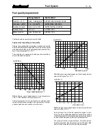
I. Checking injection timing (dy-
namic)
213--- 49
B
A
1. Warm up engine and fuel injection system.
Note!
All connections, including the magnetic probe insertion
and removal, must be done with the engine stopped.
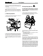
2. Remove the protective plug from access hole (
Æ
8 mm) and
attach the magnetic probe assembly
A
to the engine by insert-
ing the probe into the access hole (in tractor versions into the
upper hole), and the RETRACTING SLIGHTLY (
0,5...1,0
mm
). This must be done to prevent wear of the end of the
probe caused by contact with the flywheel. Connect the mag-
netic probe cable to the meter socket MP.
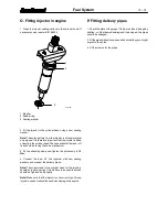
3. Install the adapter clamp
B
by first placing the clamp as-
sembly around sensor slightly above the brass contact ring
and then moving down over the contact ring. Tighten the
thumb screw of the clamp ensuring that the end of the screw
contacts the ring. Connect the transducer cable to the meter
socket SR. Connect the alligator clip to some clean unpainted
metallic portion of the fuel system or engine.
4. Turn the meter on by pressing the ON/CLEAR key. The
words ”Time Trac” and then”Model TT 1000” should appear
briefly followed by ”R= 0”. The meter can be used as a tac-
hometer at this point without further manipulation.
5. Press MAG PROBE. Display shows ”Trig Level 30%”. Press
ENTER leaving the trigger point at 30%.
6. Display shows ”Offset 20.0
˚
”. Press ENTER leaving the
offset at 20,0
˚
.
7. Display shows ”Calibrate?”. Start the engine and run it at
low idle speed. Press ENTER to continue which will cause the
display to read ”R=___ Set RPM”.
Note!
Before starting engine, make certain that all cables are
clear of any moving parts or hot manifold.
8. Once the proper RPM is displayed, press ENTER. The dis-
play shows ”Calibrating...” for a short period of time.
Note!
If for some reason the meter loses the engine speed sig-
nal or the engine is not running, the display will show ”Eng.
Not running”, flash this message 3 times, and return to the tac-
hometer mode. To restart the procedure, press MAG PROBE
(point 5).
9. If for example the engine were running at 850 RPM and tim-
ing were 6
˚
BTDC, display should now read ”R=850 MP +
6.0”. Now the meter is ready for use.
Note!
If for some reason the meter loses the magnetic probe
signal the display will show ”R=850 No Probe”. Once the
magnetic probe signal is restored, the display will show the
proper timing reading.
10. You can measure the pump timing at high idle speed [TT
(HI)]. This value is valid for pump timing setting. Adjust if
necessary. The cam advance operation of the injection pump
you can check at low idle [TT (LI)].
Setting values are available through Service Department of
Sisu Diesel Inc.
Read also manufacturer service manual.

