6
ENGLISH
The 584 PROFLAME G Fire System is designed to command any millivolt Combination Gas Control.
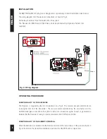
The wiring diagram of all the electrical connections is shown in Fig. 4.
Particularly shown are three main elements of the system.
The Receiver and 820 Nova mV Gas Valve can all be connected by single wire harness (not
supplied).
FUNCTIONALITY OF THE RECEIVER
The Receiver is supplied by four (4) AA batteries, see Fig. 3. The receiver accepts commands via
radio signal sent from the transmitter. The receiver sends commands by the wire harness to the
multifunctional gas control. When the system is turned on, an acoustic signal (“beep”) is generated to
indicate that the Receiver is ready to receive commands from the Remote Control.
FUNCTIONALITY OF THE REMOTE CONTROL
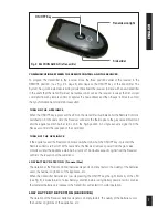
When the batteries are installed into the Remote control and the side slider is in the position shown in
Fig. 5, the LED on the transmitter illuminates each time the ON/OFF button is depressed.
INSTALLATION
OPERATING PROCEDURE
TP
TH
TPTH
Green
White
Red
Black
(+) (-)
Fig. 4: Wiring diagram.


