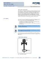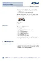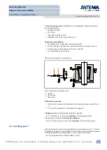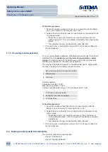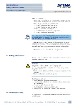
2. Series KRG moves along with the load:
KRG
direction of
movement
load
Fig. 4: Series KRG movable
4.4 Ports
All ports are uniquely identified by steel punch numbers and letters. You will
find an overview of the locations and dimensioning of all ports in the following
documents:
• in the technical data sheet
or:
• in the accompanying dimensional drawing (if provided)
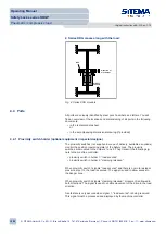
4.4.1 Proximity switch holder (optional equipment in special designs)
The proximity switches (not supplied in scope of delivery; available as options)
monitor the position (operating state) of the Safety Lock. The proximity
switches are mounted in the holders 1 and 2. They transmit the following sig-
nals to the machine controller:
• proximity switch in holder 1: “load secured”
• proximity switch in holder 2: “clamping released”
When proximity switch 1 signals “load secured” and there is no more residual
pressure at port L, the load is secured. The signal is used to allow access to
the danger zone.
When proximity switch 2 signals “clamping released”, movement is allowed in
both directions. The signal is used to enable movement of the drive in the load
direction.
A safe state is only assured when signal 1, “load secured”, is being received.
This signal must be processed and displayed by the machine controller.
Operating Manual
Safety Locks series KRGP
Pneumatic / compressive load
Original instructions BA-S12-en-1-15
© SITEMA GmbH & Co. KG . G.-Braun-Straße 13 . 76187 Karlsruhe (Germany) . Phone: +49(0)721/98661-0 . Fax: -11 . www.sitema.com
12/28


