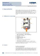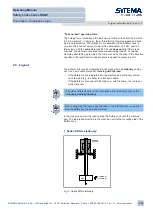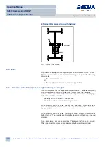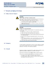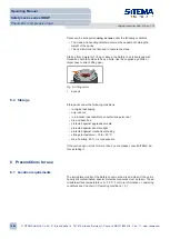
The Safety Lock withstands overloading up to 2 x admissible load (M). The
mounting elements which take up the load (such as the rod and its linkage,
etc.) must therefore be dimensioned to a loading of at least 2 x M. If the rod
is overloaded it will not slip, resulting in damage to the rod and the Safety
Lock.
7 Installation
Personnel:
•
safety engineer
•
pneumatics specialist
•
electrician
Personal protective equipment:
• goggles
• protective gloves
• safety boots
• industrial helmet
• ear defenders
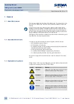
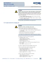
WARNING
Danger if installation is carried out improperly!
Improper installation and initial putting into service might result in serious in-
jury and major damage to assets.
Ü
Secure the danger zone.
Ü
Secure all switchable machine elements and power connections against
unintentionally being turned on.
Ü
Secure moving machine parts against dropping while carrying out work
procedures.
Ü
Leave the Safety Lock assembled. Do not open the Safety Lock.
Ü
Secure all moving parts (especially the rod and Safety Lock) separately
so that they do not drop down or topple over.
Ü
Make sure mounting screws have the required tightening torques.
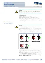
7.1 Feeding in clamping rod
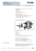
Before inserting the rod:
• Check visually:
– The interior must be free of foreign bodies and dirt.
– The wipers must not be damaged.
• Use only rods conforming to the specification.
• If there is a thread on the end of the rod, cover it.
• Provide a temporary pressure supply through a clean connection line.
• Use only a dry, ungreased rod.
Operating Manual
Safety Locks series KRGP
Pneumatic / compressive load
Original instructions BA-S12-en-1-15
© SITEMA GmbH & Co. KG . G.-Braun-Straße 13 . 76187 Karlsruhe (Germany) . Phone: +49(0)721/98661-0 . Fax: -11 . www.sitema.com
16/28

