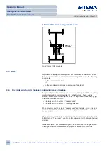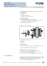
The thread dimensions are specified in the following documents:
• in the technical data sheet
or:
• in the accompanying dimensional drawing (if provided)
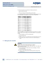
For mounting on a steel (e.g. 1.0553 / 1.0570) part, the following guide values
are recommended for the tightening torques of the mounting screws:
Thread
Strength
class
Tightening
torques
M 6
10.9 11 Nm
M 8
10.9 30 Nm
M 10
10.9 55 Nm
M 12
10.9 85 Nm
M 16
10.9 200 Nm
M 20
10.9 400 Nm
M 24
10.9 750 Nm
M 30
10.9 1 400 Nm
M 36
10.9 2 600 Nm
M 42
10.9 4 000 Nm
These specifications do not absolve the machinery manufacturer of its respon-
sibility to check the screw fittings for the specific application in a professional
manner.
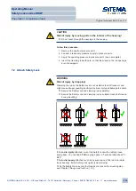
1. Move the Safety Lock to the mounting position.
2. Align the Safety Lock.
3. Make sure there are no constraint forces occurring transverse to the rod.
4. Fix the Safety Lock to the machine part with the required tightening
torque.
7.3 Making pressure connection
WARNING
Danger if the pressure fluid discharge is slowed!
Slowing of the pressure fluid discharge might cause danger, as the clamp will
then only close after a delay.
Ü
Do not integrate any components which impair discharge of the fluid
from pressure port L.
Ü
Lay all connection lines without kinking.
Ü
If there is a risk of kinking, take precautions (protective tubing, thicker
tube walling, etc.).
Operating Manual
Safety Locks series KRGP
Pneumatic / compressive load
Original instructions BA-S12-en-1-15
© SITEMA GmbH & Co. KG . G.-Braun-Straße 13 . 76187 Karlsruhe (Germany) . Phone: +49(0)721/98661-0 . Fax: -11 . www.sitema.com
18/28

