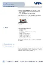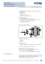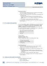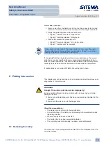
If moisture or aggressive media can be drawn in, in place of the filter install
a
depressurized line
routed directly into a clean environment, such as a
clean, depressurized vessel.
7.5 Connect proximity switch (optional equipment in special designs)
In standard designs the proximity switch holders NHT are installed. The NHT
holders are
preset
to the correct depth. Do not change the setting of the hold-
ers before installing the proximity switches. Install the proximity switches as
described in the accompanying adjustment instructions.
In the case of special designs, refer to the accompanying proximity switch
holder adjustment instructions for details of the proximity switch holder type
and all further installation and adjustment information.
7.6 Checking installation
Follow this procedure:
1. Check the lines and fittings for leaks.
2. Check that the pressure fluid is able to discharge from pressure port L
unhindered.
3. Check the free movement of the rod when pressure is applied to pres-
sure port L.
4. Check the (electrical) connection to the proximity switches.
5. Before putting the unit into service, carry out a
performance test
- see
8 Performance test
Regular performance testing ensures safe functioning of the Safety Lock.
Use the performance test to verify safe functioning of the Safety Lock also
after unforeseen events occur.
The performance test consists of the following parts:
• testing the
holding force
• Testing the
proximity switch function
(optional equipment in special de-
signs)
A performance test must be carried out in the following cases:
• after installation
• after any use at variance from the intended use
In safety applications, the functioning of the Safety Lock must be checked
at
least every 6 months
. Much more frequent testing may also be required de-
pending on the application parameters (degree of contamination, cycle fre-
quency, control system). In some cases even daily fully automated testing is
necessary. This detects any trouble at an early stage.
Operating Manual
Safety Locks series KRGP
Pneumatic / compressive load
Original instructions BA-S12-en-1-15
© SITEMA GmbH & Co. KG . G.-Braun-Straße 13 . 76187 Karlsruhe (Germany) . Phone: +49(0)721/98661-0 . Fax: -11 . www.sitema.com
20/28

