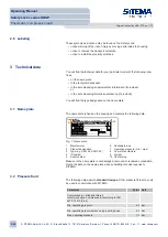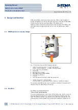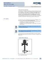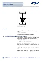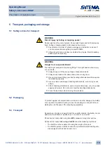
For types not listed in the data sheet you will find type-specific data on the ac-
companying dimensional drawing.
For modified standard designs you will find design-specific data in the accom-
panying supplementary information.
3.3 Operating conditions
The immediate vicinity of the Safety Lock must be dry and clean. If the unit is
heavily dirt contaminated, special protective measures must be taken - see
Chapter 6.1 Location requirements
14].
Parameter
Value Unit
Admissible surface temperature
0 – 60 °C
Max. humidity (no condensation)
60 %
Comply with the type or design specific data in the accompanying dimensional
drawing or supplement information (if provided).
3.4 Emissions
The Safety Lock creates no significant emissions.
There are no electronic components built into the Safety Lock. Consult the
manufacturer as to the electromagnetic compatibility of the proximity switches
(not supplied in scope of delivery; available as options).
3.5 Service life
When estimating service life, a distinction is made between the following cate-
gories of stress:
1. Stress when securing the load
When securing a stationary load, the occurring material stresses are negligi-
ble and can be withstood millions of times over.
2. Stress when taking up the load
When taking up the load the Safety Lock may reach the maximum holding
force. During operation this occurs, for example, when the drive is switched off
and in the event of leakage or a line break. The design forces and material
stresses then occur. The rod does not slip when this happens.
To ensure longer service life, the following operating modes should be
avoided:
• misoperation of the (press cylinder) drive with the clamp closed
• motion opposing the load direction without simultaneous pressurization
You can additionally take the following measures to extend service life:
• Make sure the rod is not subjected to any transverse forces.
• Do not use excessively rough rod surfaces.
• Protect the interior of the housing against penetration of corrosive media
and dirt.
• Clamp the rod preferably only once it has come to a complete standstill.
Operating Manual
Safety Locks series KRGP
Pneumatic / compressive load
Original instructions BA-S12-en-1-15
© SITEMA GmbH & Co. KG . G.-Braun-Straße 13 . 76187 Karlsruhe (Germany) . Phone: +49(0)721/98661-0 . Fax: -11 . www.sitema.com
9/28


