Sitex SP38 Installation and Operation
Document PN
29010101
V2r0
- 14
7
-
Appendix 4
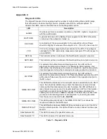
Diagnostic LEDs
The Signal Processor Unit is equipped with a number of Light-Emitting Diode (LED) lamps
that can assist in trouble-shooting should a problem arise with the autopilot system. To
observe the LEDs, remove the metal cover on the Diagnostic section.
LED
Description
ALARM
On whenever there is an alarm condition on the SPU. Lights in conjunction
with the audible alarm.
BATT PWR
A general indication of the Battery Power supplied to the SPU. Should be
on whenever the autopilot is turned on.
DRV PWR
An indication of the power available for the output Drive. Drive Power
should be brightly lit whenever the autopilot is on. If it is off, check fuse F2.
VCC
VCC is the voltage supplying the logic circuits on the SPU. The voltage is
nominally 5.25 VDC, and can be measured at test point TP3 with respect to
ground (GND).
SW’D B+
This indicator will be on whenever the Switched B+ output is turned on.
SW’D GND
This indicator will be on whenever the Switched Ground output is turned on.
M1/PORT
For systems that utilize Solenoid steering valves, this LED will be lit
whenever the solenoid is activated. For Reversing Motor systems, this
LED will be shut off whenever the motor is activated in one direction (which
direction depends on how the reversing motor was plumbed in and wired.
M2/STBD
For systems that utilize Solenoid steering valves, this LED will be lit
whenever the solenoid is activated. For Reversing Motor systems, this LED
will be shut off whenever the motor is activated in the opposite direction to
the M1 output.
NMEA 0183 IN #1
This LED will be lit whenever the autopilot receives serial data on the NAV1
input. Note that this indicator only shows that data was received. It does
not mean that the data received is valid. Typically, this LED will flash at a
rate of about once per second for regular data from a GPS or Chart plotter;
it will flash at a rate of about 10 times per second when connected to a
heading source such as an NMEA compass. If the LED does not flash and
you are sure the sending device is sending data, try reversing the wires
from the device connected to
J9
–
NAV
I/O
.
NMEA 0183 IN #2
This LED operates identically to the NMEA 0183 IN #1, but shows the
reception of data for the NAV2 input.
NMEA 0183 OUT
This LED flashes whenever NMEA 0183 serial data is sent out of the SPU.
During normal operation, this LED will flash at a rate of about ten times per
second.
Sitex
Network RX
This LED is reserved for possible future use.
Sitex
Network TX
This LED is reserved for possible future use.
Table 11 – Diagnostic LEDs
Appendices
Summary of Contents for SP38 Autopilot
Page 2: ......
Page 14: ...Sitex SP38 Installation and Operation Document PN 29010101 V2r0 13 ...
Page 15: ...Sitex SP38 Installation and Operation Document PN 29010101 V2r0 14 Introduction ...
Page 16: ...Sitex SP38 Installation and Operation Document PN 29010101 V2r0 15 ...
Page 26: ...Sitex SP38 Installation and Operation Document PN 29010101 V2r0 25 ...
Page 35: ...Sitex SP38 Installation and Operation Document PN 29010101 V2r0 34 Installation ...
Page 36: ...Sitex SP38 Installation and Operation Document PN 29010101 V2r0 35 ...
Page 74: ...Sitex SP38 Installation and Operation Document PN 29010101 V2r0 73 ...
Page 108: ...Sitex SP38 Installation and Operation Document PN 29010101 V2r0 107 ...
Page 109: ...Sitex SP38 Installation and Operation Document PN 29010101 V2r0 108 Advanced Operations ...
Page 110: ...Sitex SP38 Installation and Operation Document PN 29010101 V2r0 109 ...
Page 123: ...Sitex SP38 Installation and Operation Document PN 29010101 V2r0 122 Care and Maintenance ...
Page 124: ...Sitex SP38 Installation and Operation Document PN 29010101 V2r0 123 ...
Page 127: ...Sitex SP38 Installation and Operation Document PN 29010101 V2r0 126 Appendices ...
Page 128: ...Sitex SP38 Installation and Operation Document PN 29010101 V2r0 127 ...
Page 156: ...Sitex SP38 Installation and Operation Document PN 29010101 V2r0 155 Warranty ...
Page 157: ...Sitex SP38 Installation and Operation Document PN 29010101 V2r0 156 User Notes and Settings ...
Page 158: ...Sitex SP38 Installation and Operation Document PN 29010101 V2r0 157 ...

