Sitex SP38 Installation and Operation
Document PN
29010101
V2r0
-
50
-
Before using the SPU for the first time, please verify that the entire system and all its
components are safely and securely mounted, and will not shake loose from the vibrations
that can be expected in a marine vessel.
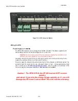
Electrical Checks for SPU
Only after all these checks have been completed should you connect the power plug into
the JI BATTERY INPUT receptacle on the SPU.
1.
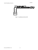
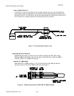
Check the power supply wiring (from the battery/breaker).
2.
Verify that the polarity and voltage are correct (use an accurate voltmeter for this).
3.
Check for correct wire size, tightness of all connections, fusing, and proper operation
of the battery power breaker or switch.
4.
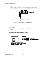
Check the connections from the Rudder Follower Unit to the SPU.
5.
Check that when the rudder is manually moved from full Starboard to full Port (and
vice-versa), that the RFU moves completely freely, and is not being restricted in any
way.
6.
Check the connections to the drive equipment from the SPU.
7.
Check that all cables are neatly routed and secured.
8.
Ensure that extraneous materials (bits of insulation, wire pieces or strands, etc.) have
been removed.
9.
If you have a magnetic sensor or a fluxgate compass, check the connections on J9
10.
If you have a NMEA 0183 compass (such as SSRC), check it is connected to NAV1
or
NAV2 port
11.
If you have an old
Sitex
CR203 or TS203, check it is connected to J10.
Caution!
During the first few weeks of operation, repeat the checks above at least
once.
Installation
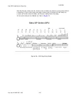
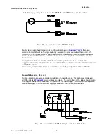
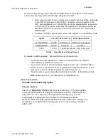
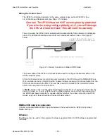
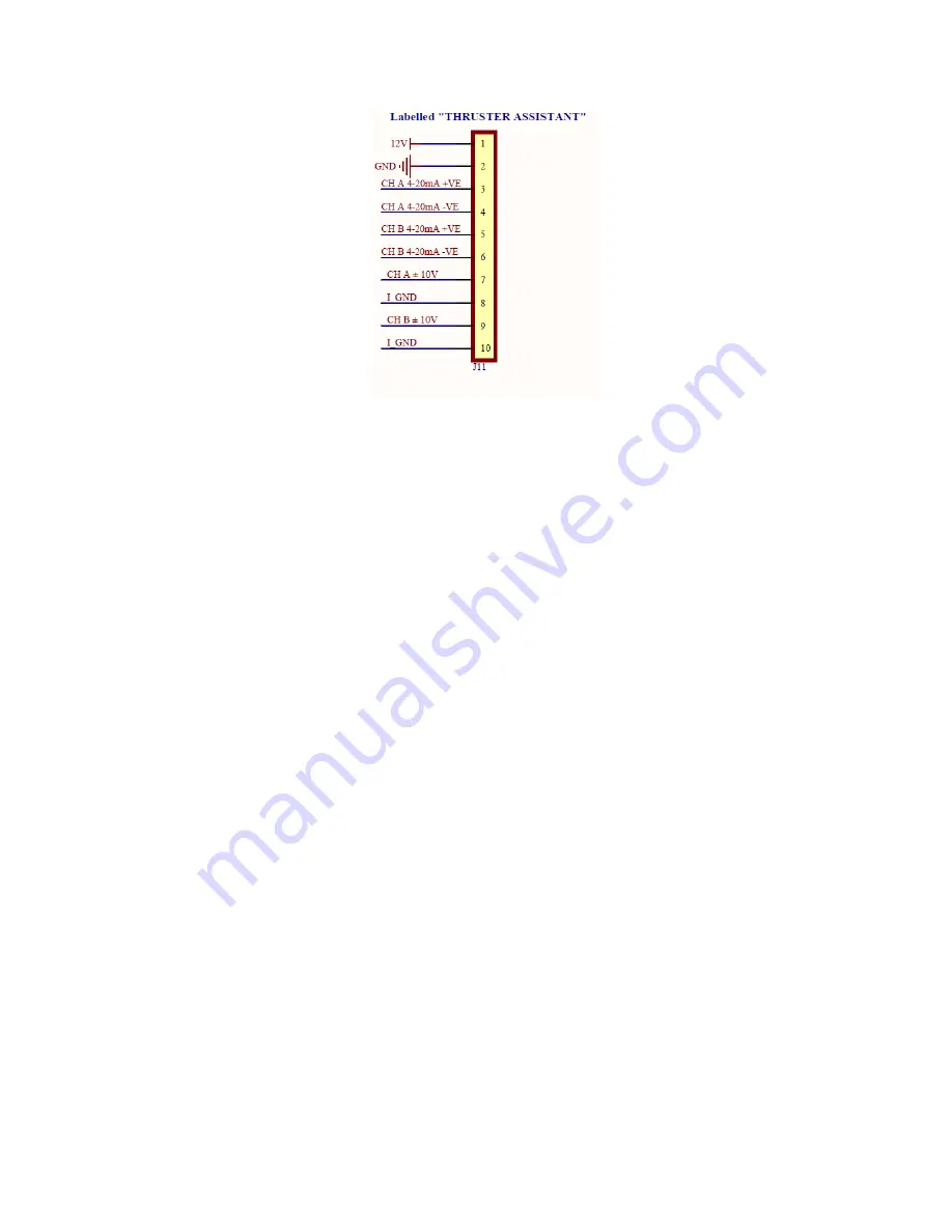
Figure 25 - Thruster
Signals for SPU-
T
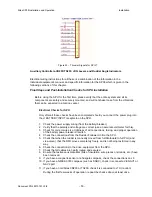
Auxiliary Controllers-CR203/TS203, JOG Levers and Rudder Angle Indicators
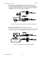
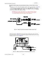
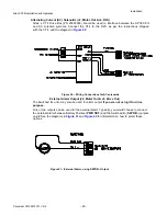
Electrical wiring instructions for all these is a combination of the information in the
individual equipment’s manual, and specific information for the
SP38
which is given in the
following sections of this chapter.
Final Steps and Post-Installation Checks for SPU installation
Summary of Contents for SP38 Autopilot
Page 2: ......
Page 14: ...Sitex SP38 Installation and Operation Document PN 29010101 V2r0 13 ...
Page 15: ...Sitex SP38 Installation and Operation Document PN 29010101 V2r0 14 Introduction ...
Page 16: ...Sitex SP38 Installation and Operation Document PN 29010101 V2r0 15 ...
Page 26: ...Sitex SP38 Installation and Operation Document PN 29010101 V2r0 25 ...
Page 35: ...Sitex SP38 Installation and Operation Document PN 29010101 V2r0 34 Installation ...
Page 36: ...Sitex SP38 Installation and Operation Document PN 29010101 V2r0 35 ...
Page 74: ...Sitex SP38 Installation and Operation Document PN 29010101 V2r0 73 ...
Page 108: ...Sitex SP38 Installation and Operation Document PN 29010101 V2r0 107 ...
Page 109: ...Sitex SP38 Installation and Operation Document PN 29010101 V2r0 108 Advanced Operations ...
Page 110: ...Sitex SP38 Installation and Operation Document PN 29010101 V2r0 109 ...
Page 123: ...Sitex SP38 Installation and Operation Document PN 29010101 V2r0 122 Care and Maintenance ...
Page 124: ...Sitex SP38 Installation and Operation Document PN 29010101 V2r0 123 ...
Page 127: ...Sitex SP38 Installation and Operation Document PN 29010101 V2r0 126 Appendices ...
Page 128: ...Sitex SP38 Installation and Operation Document PN 29010101 V2r0 127 ...
Page 156: ...Sitex SP38 Installation and Operation Document PN 29010101 V2r0 155 Warranty ...
Page 157: ...Sitex SP38 Installation and Operation Document PN 29010101 V2r0 156 User Notes and Settings ...
Page 158: ...Sitex SP38 Installation and Operation Document PN 29010101 V2r0 157 ...

