Sitex SP38 Installation and Operation
Document PN
29010101
V2r0
- 5
9
-
System Setup
A minimum
SP38
Autopilot system requires these components: An
SP38
SPU, a
SP38
controller
(Head), and two main inputs: A Heading Source plus a Rudder Follower Unit or Interface
.
By default, the SPU looks
for
heading data from the NMEA 2000 network. The Heading
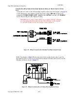
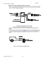
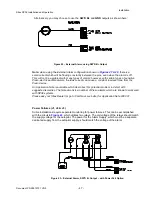
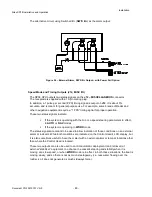
may come from other connection ports on the SPU. Refer to
o
ther equipment in Appendix
for how to use a
Sitex
Magnetic Compass, a Fluxgate compass, Rate Compass or other
NMEA 0183 compliant compasses.
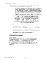
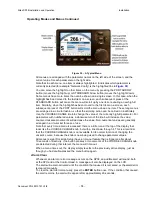
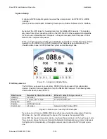
When you have wired and verified your installation as described, the first time the system is
powered on, the
SP38
SPU and
SP38
Head will link themselves up automatically. You
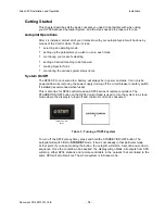
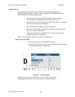
should be able to see on
SP38
Head the system enters Standby mode.
208.6
3.0
First time power on
The first time you power on your system,
SP38
SPU will also search for suitable data
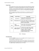
sources it needs in various operations from the NMEA 2000 network. The following table
shows what data are used for SPU
Data Source
Required in Operation modes
Where to select/change a source
Heading
All modes
Network Config
Rudder
P. Steer, AUTO, NAV
Fixed from RFU port
Navigation
NAV
Position
AUTO ALC mode
Control unit
All modes
Network config=>Linked SPU
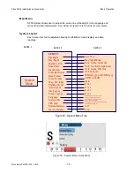
Figure
31
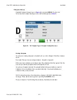
- Autopilot in Standby Mode
Figure
32
- Data sources used by
SP38
Autopilot
If you have more than one NMEA 2000 device that can provide the same type of data the
SPU looks for, the SPU will pick up the device it first receives the required PGN.
Once SPU has found and saved a device, it will use the same device in the next power cycle.
You can only change this source through the Network Configuration menu (refer to Network
Config Menu for more details), or through a network reset to allow the SPU to pick a new
one.
Installation
Summary of Contents for SP38 Autopilot
Page 2: ......
Page 14: ...Sitex SP38 Installation and Operation Document PN 29010101 V2r0 13 ...
Page 15: ...Sitex SP38 Installation and Operation Document PN 29010101 V2r0 14 Introduction ...
Page 16: ...Sitex SP38 Installation and Operation Document PN 29010101 V2r0 15 ...
Page 26: ...Sitex SP38 Installation and Operation Document PN 29010101 V2r0 25 ...
Page 35: ...Sitex SP38 Installation and Operation Document PN 29010101 V2r0 34 Installation ...
Page 36: ...Sitex SP38 Installation and Operation Document PN 29010101 V2r0 35 ...
Page 74: ...Sitex SP38 Installation and Operation Document PN 29010101 V2r0 73 ...
Page 108: ...Sitex SP38 Installation and Operation Document PN 29010101 V2r0 107 ...
Page 109: ...Sitex SP38 Installation and Operation Document PN 29010101 V2r0 108 Advanced Operations ...
Page 110: ...Sitex SP38 Installation and Operation Document PN 29010101 V2r0 109 ...
Page 123: ...Sitex SP38 Installation and Operation Document PN 29010101 V2r0 122 Care and Maintenance ...
Page 124: ...Sitex SP38 Installation and Operation Document PN 29010101 V2r0 123 ...
Page 127: ...Sitex SP38 Installation and Operation Document PN 29010101 V2r0 126 Appendices ...
Page 128: ...Sitex SP38 Installation and Operation Document PN 29010101 V2r0 127 ...
Page 156: ...Sitex SP38 Installation and Operation Document PN 29010101 V2r0 155 Warranty ...
Page 157: ...Sitex SP38 Installation and Operation Document PN 29010101 V2r0 156 User Notes and Settings ...
Page 158: ...Sitex SP38 Installation and Operation Document PN 29010101 V2r0 157 ...

