Sitex SP38 Installation and Operation
Basic Operation
Document PN
29010101
V2r0
-
90
-
Auto/Nav Limits
The Auto/Nav Limits are essentially the same as the Power Steer Limits detailed above, but
they are in effect only when the autopilot is in
AUTO
or
NAV
modes.
RAI Offset
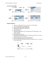
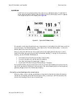
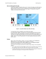
The Rudder Angle Indicator (RAI) display at the bottom of the autopilot display may require a
slight offset adjustment in order to read zero degrees when the vessel is moving in a straight
line. This is a fairly common scenario and may be due to vessel loading or design, rudder
design or function, or the installation of the Rudder Feedback Unit. For example, if the vessel
is traveling in a straight line, but the RAI reads 2° to starboard, adjust the RAI Offset to port
so that the RAI display reads zero.
Stdby/P. Str Limits - Power Steer Rudder Limits
When you initially set up the
SP38
system, you will
move the rudder from hard over port to hard over starboard so that the autopilot can measure
these positions. These mechanical hard over positions are known as the “physical limits”,
beyond which the rudder simply cannot be turned. However, you can artificially limit the
rudder travel through the autopilot software.
To do so, set the Power Steer
Limits to the number of degrees port and starboard that you
would like to limit the rudder movement to. These rudder limits will be in effect whenever the
autopilot is in POWER STEER mode, and during all Dodge and Jog Lever turns. The
minimum setting is 5°; the maximum is the same as the physical limits measured in Dockside
Setup. Setting the limits to “Off” means that the full range – up to the physical limits – will be
allowed. The range beyond the selected limits will be shown on the bottom bar of the Rudder
Angle Indicator display during normal operation.
NOTE: SPU firmware versions before 3.05 allowed the rudder to be moved in Standby mode
with a Jog Lever. However, this feature was disabled in that version and onwards, for safety
reasons. The parameter name in the menu was not changed, however.
Summary of Contents for SP38 Autopilot
Page 2: ......
Page 14: ...Sitex SP38 Installation and Operation Document PN 29010101 V2r0 13 ...
Page 15: ...Sitex SP38 Installation and Operation Document PN 29010101 V2r0 14 Introduction ...
Page 16: ...Sitex SP38 Installation and Operation Document PN 29010101 V2r0 15 ...
Page 26: ...Sitex SP38 Installation and Operation Document PN 29010101 V2r0 25 ...
Page 35: ...Sitex SP38 Installation and Operation Document PN 29010101 V2r0 34 Installation ...
Page 36: ...Sitex SP38 Installation and Operation Document PN 29010101 V2r0 35 ...
Page 74: ...Sitex SP38 Installation and Operation Document PN 29010101 V2r0 73 ...
Page 108: ...Sitex SP38 Installation and Operation Document PN 29010101 V2r0 107 ...
Page 109: ...Sitex SP38 Installation and Operation Document PN 29010101 V2r0 108 Advanced Operations ...
Page 110: ...Sitex SP38 Installation and Operation Document PN 29010101 V2r0 109 ...
Page 123: ...Sitex SP38 Installation and Operation Document PN 29010101 V2r0 122 Care and Maintenance ...
Page 124: ...Sitex SP38 Installation and Operation Document PN 29010101 V2r0 123 ...
Page 127: ...Sitex SP38 Installation and Operation Document PN 29010101 V2r0 126 Appendices ...
Page 128: ...Sitex SP38 Installation and Operation Document PN 29010101 V2r0 127 ...
Page 156: ...Sitex SP38 Installation and Operation Document PN 29010101 V2r0 155 Warranty ...
Page 157: ...Sitex SP38 Installation and Operation Document PN 29010101 V2r0 156 User Notes and Settings ...
Page 158: ...Sitex SP38 Installation and Operation Document PN 29010101 V2r0 157 ...

