background image

 9 


 12 


TROUBLESHOOTING 


  YES 


NO 

YES, no problem 

NOK 

YES, no problem 

NO 

YES 

NO 

YES 

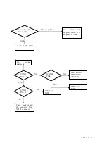
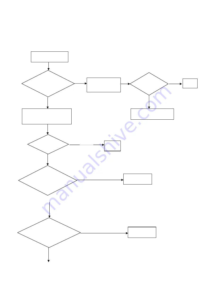
No picture 

Can see   
the 

PRESET 

menu? 

IC N301 Pin3

IC 

N302 Pin5 (H&V 
SYNC output)? 

IC  N301  Pin10,  IC 
N302 Pin2(H&V 
input )


Replace  
N301 or N302 

Can see 
picture? 

Set “

black screen

” 

in 

OPTION1

 to 

“off”

Replace N304 

Change the teletext board 
(E/RSAG7.820.234A) 

OK 

Check the cables from XP312 
to XP110 

XP311 to XP102 

Can see 
picture? 

NOK 

YES 

OK 

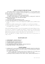
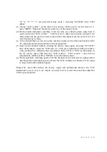
Summary of Contents for LCD1701EU

Page 1: ...第 1 页 共 12 页 LCD1701EU LCD2001EU LCD1702EU LCD2002EU SERVICE MANUAL V1 1 DECEMBER 28 2004 ...

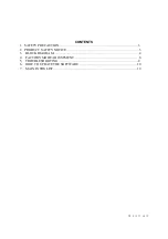
Page 2: ...第 2 页 共 12 页 CONTENTS 1 SAFETY PRECAUTION 3 2 PRODUCT SAFETY NOTICE 3 3 BLOCK DIAGRAM 4 4 FACTORY MODE ADJUSTMENT 6 5 TROUBLESHOOTING 8 6 HOW TO UPDATE THE SOFTWARE 10 7 MAIN PATRS LIST 10 ...

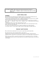
Page 3: ...resistor 10mm 1 2in away from circuit board 5 Connection wires must be kept away from components with high voltage or high temperature 6 If any fuse in this TV receiver is blown replace it with the FUSE specified in the chassis parts list PRODUCT SAFETY NOTICE Many electrical and mechanical parts in the chassis have special safety related characteristics These characteristics are often passed unno...

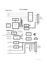
Page 4: ...DIO IN GPIO I2 C 8V 33V 12V 5V 2ndSIF mono signal H V B G V H B G R Pr Cr Pb Cb PI5V330 N304 TUNER A201 STV2248 N201 SAA5264 NB01 74HC123 N302 74HC123 N301 TDA9181 N303 MSP3410G N202 Y TDA1517 N203 LM358 N204 LM317 N501 BA6161N N502 XP312 XP311 SCART TO MAIN BOARD FROM MAIN BOARD ...

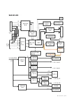
Page 5: ...7 3 3V N107 12V 12V PC VGA 74HC4053 N102 PI5V3 30 N104 74LVC32 N103 PW1306 N107 DS90C383 N118 IR KEYPAD 74LV541 N109 74LV273 N113 PANEL 17 MCU INVERTER PANEL 20 INVERTER AM29LV800 N105 LM2576 N108 IRF7314 N110 IRF7314 N111 LM1117 N115 LM1117 N117 LM1117 N116 LM1117 N114 LM358 N119 IRF7314 N112 INVERTER XP110 PANEL INVERTER ...

Page 6: ... white balance picture modes value SCART Audio out value and volume middle value And the contrast value AGC value and the important value vcofine vcocoa are in the sub menu 2248 adjust 5 In OTHER menu select the item you want to adjust by pressing the button CH or CH such as sharpness adjust Volume Max and Volume Min value and use the VOL or VOL button to adjust 6 Press MENU button on the remote c...

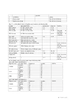
Page 7: ...ce Wb auto adj Automatically adjust white balance Used for test in factory Wb state preset White balance state value Used for test in factory Pct mode setting Picture modes value of different source SCART Audio out Audio out amplitude value 96 80 116 Volume Middle Middle value of volume 100 0 127 Channel set Used for test in factory Pump current 1 0 7 Used for test in factory Set the default value...

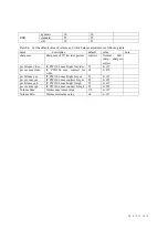
Page 8: ...ft sharp sharpest softest pw brt max video IC PW1306 max bright for video 35 0 127 pw cnt max video IC PW1306 max contrast for video 65 0 255 pw brt max yuv IC PW1306 max bright for yuv 55 0 127 pw cnt max yuv IC PW1306 max contrast for yuv 85 0 255 pw brt max rgb IC PW1306 max bright for rgb 55 0 127 pw cnt max rgb IC PW1306 max contrast for rgb 85 0 255 Volume Max Volume maximum value 110 0 127 ...

Page 9: ...the PRESET menu IC N301 Pin3 IC N302 Pin5 H V SYNC output IC N301 Pin10 IC N302 Pin2 H V input Replace N301 or N302 Can see picture Set black screen in OPTION1 to off Replace N304 Change the teletext board E RSAG7 820 234A OK Check the cables from XP312 to XP110 XP311 to XP102 Can see picture NOK YES OK ...

Page 10: ... IC N202 PIN24 25 IC N202 PIN47 IC N202 PIN4 6 REPLACE N202 CHECK INPUT PERIPHERY CIRCUIT REPLACE N202 Check IC N201 Pin 45 8V NOK Check L205 N501 Check N201 5V supplier SAW 33V supplier TUNER YES NO YES Check speakers and the connector from XP203 to speakers ...

Page 11: ...rk will erase all the parameter such as white balance value vco value etc So before you update the software you must enter the factory mode and to write down the vco values and white balance values When you finish the updating work you must restore those values to right position If not the LCDTV will not memory channel and the picture will be bad and not in right colour MAIN PARTS LIST 1 TUNER BOA...

Page 12: ...and sound are in the best position f Keep current channel number entering the factory menu again choosing STV2248 then 2248 adjust select the 2248 auto vco item press right narrow button to make it work waiting for a while less than one minute there will be a OK on the bottom of the TV screen and at that time the 2248 vcofine 2248 vcocoa value will be automatically calibrated Press MENU to exit th...

Reviews: