ST-800/900
Maintenance manual
13
11.6.2
、
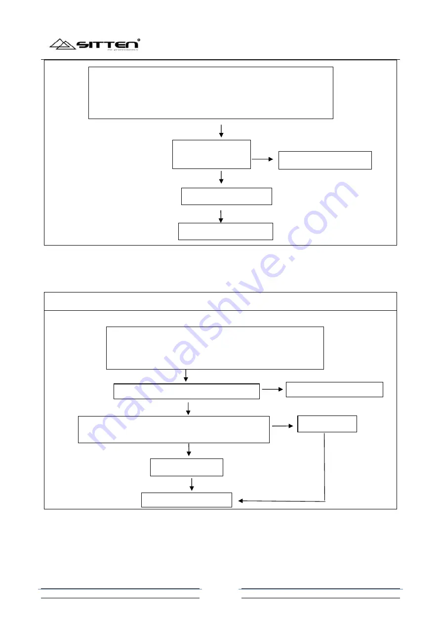
The emitting tube of the dial sensor
The maintenance of the emitting tube of the dial sensor circuit
11.7
、
Chart 7: The maintenance of the motor control circuit
11.7.1
、
The main motor control circuit
In the batching mode, input “1.2.3.4” then press “RESET”; when the display
show “ U00 A00”, rotate the feeding roller by hand slowly, measure the
voltage of 3
rd
pin of J17 by digital multimeter, and observe the voltage can
change between 0.15V to 4.3V.
Whether the receiving
tube is damaged or not
N
CPU or U4 is damaged
N
Y
Replace the dial sensor
Replace the main board
In the batching mode, input “1.2.3.4” then press “RESET”; when
the display show “ U00 A00”, measure the voltage of 2
nd
pin of J17
by digital multimeter, and the voltage is around 1.14V.
Whether the emitting tube is damaged or not
N
The voltage of b pole of Q8 is around 4.11V, and the
voltage of 30
th
pin of CPU is around 0.05V.
N
Y
CPU is damaged
Replace the emitting tub
Y
Q8 is damaged
N
Replace the main board


