2.1 Brief Introduction
Paris500 plasma cutting machines adopts the latest pulse width modulation (PWM)
technology and insulated gate bipolar transistor (IGBT) power module, which can change
work frequency to medium frequency so as to replace the traditional hulking work frequency
transformer with the cabinet medium frequency transformer. Thus, its characterized
with portable, small size, light weight, low consumption and etc.
Paris500 plasma cutting machines Characteristics:
◆
IGBT technology
◆
With EMI filter to minimize the pollution of the electrified net
◆
High mains voltage tolerance
±
15%to maintain stable work
.
◆
MCU control system, responds immediately to any changes.
◆
Excellent cutting capability.
◆
P
ilot arc controller, can cut grid workpiece
2.2 Specifications
Description
Weight
Power Source Dimensions
Cooling
Welder Type
European Standards
Number of Phases
Nominal Supply Voltage
Nominal Supply Frequency
Welding Current Range
Single Phase Generator Requirement
Welding Output, 40ºC, 10 min.
Open circuit voltage
Protection Class
Quality Cutting Thickness
(500mm/min)
Maximum Cutting Capacity
Maximum Input Current
Effective Input Current
SIWM DIGITAL Paris500
7.1 kg
Fan Cooled
Inverter Power Source
EN 60974-1 / IEC 60974-1
1
230V +/- 15%
50/60Hz
20 - 50A
18.6A
37.2A
9.9kVA
50A @ 30%, 100V / 27.4A @ 100%, 91V
240V DC
IP23
8mm
(
Steel cutting capability / Thickness to scale.)
12mm
(
Steel cutting capability / Thickness to scale.)
◆
occoured, the alarm lamp on the front panel will be on and the output current will
be cut off. It can self-protect and prolong the using life.
Intelligent protection: over-current, over-heat, when the mentioned problems
CUTTING
SERIES
EQUIPMENT
Summary
2.3 Duty Cycle
2.4 Packaged Items
Due to variations that can occur in manufactured products, claimed performance, voltages,
ratings, all capacities, measurements, dimensions and weights quoted are approximate
only. Achievable capacities and ratings in use and operation will depend upon correct
installation, use, applications,maintenance and service
◆
Plasma Torch 4m PT-31
◆
300A earth clamp with 2.5m cable
◆
3m Power cable
◆
3.5m Gas Hose 8x13.5
◆
Operating Manual
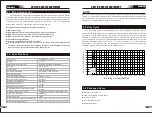
The rated duty cycle of a Welding Power Source is a statement of the time it may be
operated at its rated welding current output without exceeding the temperature limits of the
insulation of the component parts. To explain the 10 minute duty cycle period the following
example is used. Suppose a Welding Power Source is designed to operate at a 30% duty
cycle, 50 amperes at 100 volts. This means that it has been designed and built to provide
the rated amperage (50A) for 4 minutes, i.e. arc welding time, out of every 10 minute
period (30% of 10 minutes is 4 minutes). During the other 6 minutes of the 10 minute period
the Welding Power Source must idle and be allowed to cool.
D
u
ty C
y
c
le
(P
E
R
C
E
N
T
A
G
E
)
Welding Current(AMPS)
25
50
75
100
1
25
150
175
0
10
20
30
40
50
60
70
80
90
100
2
0
0
2
25
2
5
0
275
3
00
0
Safe
Operating
Region
NOTE
Summary
CUTTING
SERIES
EQUIPMENT
H320mmxW/160mmxD380mm
07
06


