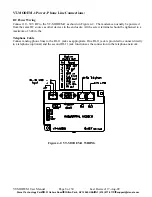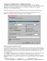
VT-MODEM-3 Power, Phone Line, RS422 / RS485 Connections:
DC Power Wiring
Connect 10 - 52 VDC to the VT-MODEM-3 as shown in Figure 4-4. The modem can usually be powered
from the same source as other devices in the enclosure. All the screw terminals should be tightened to a
maximum of 3.48 in-lbs.
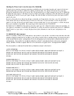
Telephone Cable
Connect an analog phone line to the RJ-11 jack as appropriate.
RS422 / RS485 Cabling and DIP Switch Settings
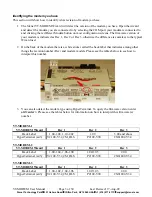
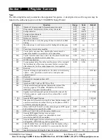
Refer to Figure 4-4 for typical wiring configurations. Fabricate a cable to connect the modem's RS422 /
RS485 port to the field device(s).
The VT-MODEM-3 has DIP switches. These switches establish the mode of operation for the RS422/RS485
port. Set these switches to match the type of wiring connected to the RS422/RS485 port. Refer to Figure 4-5
on the next page. It is not necessary to cycle power to the modem if DIP switch changes are made.
Figure 4-4: Typical RS422 / RS485 Wiring
VT-MODEM User Manual
Page 10 of 30
Last Revised: 17-Aug-09
Sixnet Technology Park
331 Ushers Road
Clifton Park, NY 12065 USA
+1 (518) 877-5173
support@sixnet.com


