background image

31 


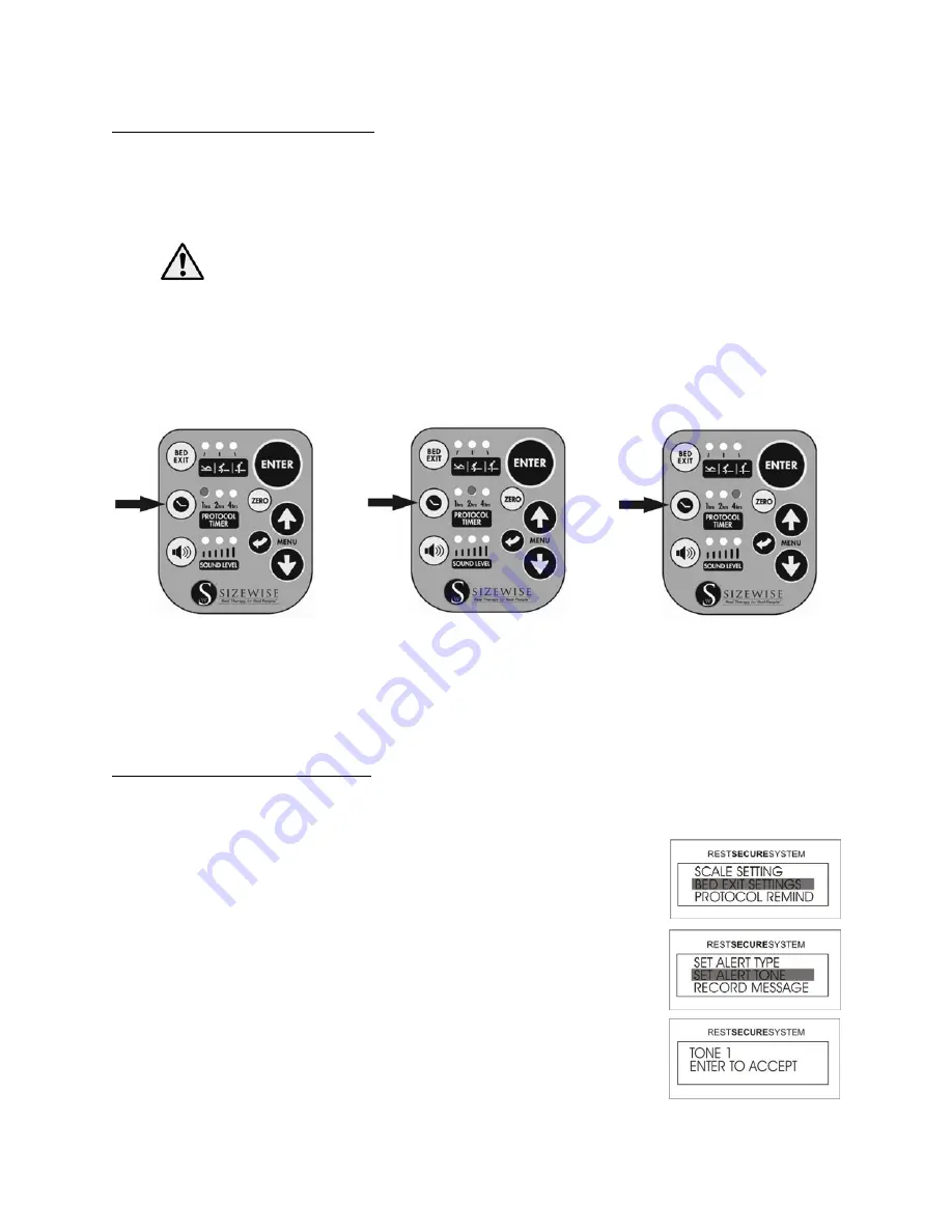
Protocol Timer: Using the Timer 

The SW Rest Secure System™ protocol timer can be utilized to alert the care provider that the 
patient needs to be attended to or checked on at intervals of 1, 2 or 4 hours.  The protocol timer 
has the capability to alert the care provider by an audible tone on the unit and, if connected to the 
Nurse Call Interface, can activate the nurse call signal. 
 

WARNING:  

The bed is to be used in accordance with each facility’s policies and 

procedures. 

 
Press the PROTOCOL TIMER button once to set the timer to 1 hour, press it twice to set the timer 
to set to 2 hours, press it three times to set to 4 hours.  By pressing the PROTOCOL TIMER button 
a fourth time, the timer will be disabled and no indicator lights will be lit.  When a protocol alarm 
has been activated, simply press the ENTER button to reset the alarm and repeat the timing process.  


NOTE: 

On alarm, the unit must first be reset by pressing ENTER before the protocol timer can 

be changed. 
 
The sound level on the protocol timer can be changed, see the section Unpacking and Set-Up 
Instructions Protocol Timer: Sound Level Setting on page 27 to learn how. 
 

Bed Exit Alarm: Set Alert Tones 

There are 5 different audible alarm tones for the bed exit alarm.  The user will hear each of the 
different tones as they scroll through the 5 selections. 
 

1.


Access the Menu by pressing the UP or DOWN arrow until Bed 
EXIT SETTINGS is highlighted and then press ENTER. 


2.


Select SET ALERT TONE and then press ENTER. 


3.


Using the arrows, select one of the 5 tones and then press ENTER.  
The selection has now been completed and the user will return to 
the Home Screen.  


1 Hour 

2 Hours

4 Hours 

Summary of Contents for Bari Rehab Platform 3 Series

Page 1: ...1 User Manual Bari Rehab Platform 3 8113 Rev 2 0 2 26 2021 ...

Page 2: ...2 Declaration of Conformity ...

Page 3: ...s 10 Description of the SW Rest Secure System RSS 12 SW Rest Secure System Specifications 13 RSS Control Module 13 RSS Hand Control 14 Description of the Power Drive 15 Power Drive Specifications 16 Unpacking and Set Up Instructions 17 Unpacking Parts Breakdown 17 Bed Set Up 18 Side Rail Set Up 21 Read and fully understand operator s manual before using this device Failure to follow operating inst...

Page 4: ...m Use Scale and Access Weight History 30 Protocol Timer Using the Timer 31 Bed Exit Alarm Set Alert Tones 31 Bed Exit Alarm Record Message 32 Scale System Adjust Weight 32 Scale System Change LBS KGS Setting 33 Scale System Locking Unlocking the Unit in LBS KGS 33 Power Drive Operating Instructions 34 Additional Driving Instructions 35 In Patient Cardiac Situation 35 Proper Use of the Bed 36 Reach...

Page 5: ...neral Safety 54 Pinch Point 54 Transport 55 Cleaning Instructions 56 Laundry Instructions 60 Optional Accessories 61 Maintenance 62 Service Replacement of Hand Control 63 Lubricating the Actuators 63 Fasteners 64 Storage and Disposal 64 Troubleshooting 65 Bari Rehab Platform 3 Troubleshooting 65 SW Rest Secure System Troubleshooting 66 Power Drive Troubleshooting 67 Touchpad Flash Codes 67 Warrant...

Page 6: ...result in patient and or user injury as well as damage to equipment Electrical Shock Hazard Warning This symbol is intended to alert the user to the presence of electrical shock hazards It s important to follow all instructions and special procedures to avoid electrical shock to the operator care provider and or patient Pinch Point Hazard Warning This symbol is intended to alert the user to the pr...

Page 7: ...8mm 0 315 or 25mm 0 984 Protective Earth Terminal Grounding symbol It is placed at the equipment earth ground point and is mandatory for all grounded equipment AP Anesthetics Proof For medical equipment intended for use in ordinary locations but likely to be brought into the operating or delivery room Located on the ECM Located on the ECM The hazards and warnings are indicated on the shipping cont...

Page 8: ...ized by the manufacturer Many of the screws and bolts used in the bed are special high strength fasteners Contact an authorized Sizewise technician to assist in finding the correct fasteners If improper fasteners are used they could result in patient and or user injury as well as damage to equipment or other property Only authorized personnel should engage in the troubleshooting process Troublesho...

Page 9: ...om a low position of 15 75 39 cm to a high position of 30 76 cm The frame is designed to support a safe working load of up to 1 000 lbs 453 kg The bed is standard equipped with four 5 heavy duty casters headboard and footboard a manual emergency crank four electric drive modules a set of four side rails and a hand control Options include Trapeze Line Management O2 Holder Pillow Speaker Power Outle...

Page 10: ... US models Fuses 10 amp time delay Overall Width 39 99 cm 41 5 105 5 cm 48 122 cm 50 5 128 5 cm Overall Length 80 203 cm 96 244 cm 86 218 5 cm 102 259 cm Length Regular 84 5 215 cm Extra Tall 90 5 230 cm Between Head Footboard Deck Low without mattress 15 75 39 cm Deck High without mattress 30 76 cm Trendelenburg 15º Reverse Trendelenburg 15º Head Section 64º Knee Section 35º Foot Section 10º Angl...

Page 11: ...s 22 kg Optional Trapeze 850 lbs 385 kg Exceeding these limits will void the warranty WARNING Exceeding the weight capacity and or safe working load listed in the specifications could result in patient or user injury as well as damage to equipment or other property ...

Page 12: ...n alarm will sound either at the hand control or activate the nurse call signal The SW Rest Secure System also has an integrated scale that utilizes a transducer based system to accurately record the weight of the patient while in the bed It also has the capability to record the weight automatically every day for 30 days at user defined intervals Another feature is the protocol timer which can be ...

Page 13: ...n 0 Ohms Alarm 0 3 Ohms Output 0 206 VRMS Max External Power AC Adapter 12 0 Volts DC Medical Grade supply Current 800 mA 1 25 A Battery Power Type 6V SLA Capacity 3 5 AH Recharge Time fully discharged 12 15 hours Operating Time No Alarms 8 hours Operating Current Normal 300 450 mA Charging 600 mA Alarming 320 mA Weighing Function Resolution 1 lb 0 45 kg Weight Stability 1 lb Averaging 16 samples ...

Page 14: ...ound Level 90 dB 12 inches 30 48 cm Tones 5 selectable tones Display Type LCD Graphic blue LED backlighting Size 64 mm x 17 9 mm 2 52 x 705 Resolution 32 Pixels Functions Bed Exit Alarm Sensitivity Levels Off Low Medium High Protocol Timer Alarm Off 1 2 4 Hours Sound Volumes Off Low Medium High Scale 0 1000 lbs 0 453 5 kg Scale Accuracy 4 lbs Scale accuracy can only be achieved by proper factory c...

Page 15: ...der is able to access the controls It is not intended nor has the ability for the patient to use any mobility controls WARNING Be sure to secure the patient before operating the power drive WARNING Avoid feet in the path of the bed when using the power drive The power drive is powered by two 12V 26AH SLA sealed lead acid batteries The drive includes a charging system to recharge the batteries when...

Page 16: ...ower Type 2 12V SLA Sealed Lead Acid Capacity 26 AH Recharge Time recommended maximum 12 hours Operating Time 2 hours Operating Current Normal 13 Amps Charging 2 6 Amps Alarming Battery Charge indicator on Touchpad Operating time may vary depending on the patient load and options the bed is equipped with ...

Page 17: ...ttress Stop Power Drive Information Packet Assembly Bolts The bed requires four bolts two on each side as indicated A to connect the head and the foot mainframe sections together The bolts must be 5 16 18 x 2 1 2 long Grade 8 Hex Head Cap Screws There are no exceptions or substitutions to this requirement Sizewise part number is 27001204 Tools required for assembly Phillips Screwdriver 3 16 Allen ...

Page 18: ... the bed 3 Install the 5 16 18 x 2 1 2 long Grade 8 bolts C through the top holes on the brackets to lock the two sections together Install and tighten the nuts on the 4 bolts WARNING Failure to securely fasten the four bolts in place during bed set up could result in patient or user injury as well as damage to equipment or other property 4 Locate the headboard and footboard mount them on their re...

Page 19: ...rovided and the hand control cord to the ECM 8 The hand control for the bed is routed to the center of the bed and should be routed to exit the bed either on the left or the right side hanger hooks are provided to secure the cable from the floor 9 Install the mattress stop bar rail Carefully remove the protective covering from the mattress Slide the mattress onto the bed frame NOTE DO NOT use a sh...

Page 20: ...et Locate the ON OFF switch on the ECM and switch it to the ON position WARNING To avoid electrical shock when plugging this bed into the wall outlet only use grounded or hospital grade outlets WARNING Follow EMC guidelines and safety precautions when the bed is connected to powered source page 47 Radio wave sources such as radio stations TV stations amateur radio HAM transmitters two way radios a...

Page 21: ...us injury can result These guidelines can be found on the FDA website It is the care provider s ultimate decision whether or not to use bed rails with the patient To Mount 1 Align the side rail mount with the two pre drilled holes A located toward the center of the top deck and place the bolts through the holes 2 Place the nut on the bolt underneath the deck and tighten 3 Slide the side rail into ...

Page 22: ...pment or other property WARNING Electrical shock or malfunction may occur if the hand control cord is pinched or frayed Keep the cord away from moving parts Turn ON the bed by switching the ON OFF switch located on the Electronic Control Module The buttons perform the following operations A CPR B Puts bed in Chair position C Raises head section of bed D Raises foot section of bed E Lowers head sec...

Page 23: ...Use to set the bed exit alarm E Enter Button Use for making a selection when in the main and sub menus F Protocol Timer Button Use to set the protocol reminder G Zero Button Use for zeroing the scale and establishing the tare weight base weight H Sound Level Button Use for selecting low medium and high volume I Up Down Arrow Menu Buttons Use for accessing the menu and making adjustments to menu it...

Page 24: ...BS Battery 100 Charge Low Battery Warning 10 00 Ma y18 20 10 REST SYSTEM SECURE S 250 LBS x The unit will go into standby after 60 seconds of inactivity If this occurs press any button except back to resume CAUTION To ensure reliable functionality the battery reserve should only be used as a temporary power source until AC power is restored When the Low Battery Warning screen is shown the unit sho...

Page 25: ...te the mattress prior to zeroing the scale Adding or removing items during the zeroing process will cause inaccurate patient weight It is highly recommended that the scale be zeroed before each new patient Scale System Adding Removing Items The feature will allow items to be added and removed such as blankets or pillows from the bed without affecting the current weight reading of a patient 1 Acces...

Page 26: ...me must be set in 24 hour clock in 1 2 hour intervals Example 13 00 1 00 pm Protocol Set Alert Reminder The protocol reminder is a timer that can be set for 1 2 or 4 hours as a reminder that the patient needs to be attended to or checked on There are three alert settings for the protocol alarm 1 Access the Menu by pressing the UP or DOWN arrow until PROTOCOL REMIND is highlighted and then press EN...

Page 27: ...l indicator lights will be OFF This indicates that the sound level has been disabled Setting the Time Date 1 Access the Menu by pressing the UP or DOWN arrow until SYSTEM SETTINGS is highlighted and then press ENTER 2 Select SET TIME DATE and then press ENTER 3 Using the UP or DOWN arrow the user can now set the hours and then press ENTER The time must be set in 24 hour clock 13 00 1 00 pm 4 Using...

Page 28: ...he UP or DOWN arrow the user can set the date and then press ENTER 8 Using the UP or DOWN arrow the user can now set the year and then press ENTER After pressing ENTER the user will return to the SET TIME DATE menu To get back to the Home Screen press and hold the BACK button for 3 seconds ...

Page 29: ...ted the bed This setting would typically be used by the care provider in situations where the patient responds to verbal or audible commands and is at a lower risk for falls If the patient is on an air support surface a lower sensitivity setting may be more appropriate as well NOTE High and medium sensitivity settings may detect other movement such as air therapy mattresses High Sensitivity Medium...

Page 30: ...roviders convenience in attending to the patient Before a patient is placed into the bed the scale should be zeroed out See the section Unpacking and Set Up Instructions Scale System Zeroing the Scale on page 25 1 Access the Menu by pressing the UP or DOWN arrow until SCALE SETTINGS is selected and then press ENTER 2 Select WEIGHT HISTORY and then press ENTER 3 Using the arrows the user can toggle...

Page 31: ...tor lights will be lit When a protocol alarm has been activated simply press the ENTER button to reset the alarm and repeat the timing process NOTE On alarm the unit must first be reset by pressing ENTER before the protocol timer can be changed The sound level on the protocol timer can be changed see the section Unpacking and Set Up Instructions Protocol Timer Sound Level Setting on page 27 to lea...

Page 32: ...rd a message by speaking directly into the microphone The message can be recorded for a maximum length of 15 seconds 4 When the recording is finished release the ENTER button and follow the on screen prompts Scale System Adjust Weight This feature is designed to manually adjust the weight if items were added to the bed without using the Add Remove option The user will need to make sure the patient...

Page 33: ...S and then press ENTER 4 The unit will return to the Home Screen showing the weight in kilograms or pounds dependent upon which was chosen Scale System Locking Unlocking the Unit in LBS KGS As part of a safety feature this unit has the ability to lock the unit of measure in lbs or kg This will prevent accidently changing the units in the Scale Settings menu 1 Access the menu by pressing the UP or ...

Page 34: ...dicates the remaining battery charge Can also assist with troubleshooting of the power drive see Table 1 on page 67 D ON OFF Switch The main power switch OFF manual mode drive wheel is retracted ON transport mode drive wheel is lowered E Horn Warns others of approach F Emergency Switch Shuts off the device in an emergency situation when it cannot be shut down in the usual manner G Acceleration Con...

Page 35: ...trol Throttle and the device will begin to move The more you squeeze the throttle the faster it will go To stop release lever NOTE If the attendant is squeezing the throttle when turning on the system the device will go to a default Flash mode If this happens turn the system off ON OFF switch on the controls and restart the power drive Additional Driving Instructions To steer device turn handle in...

Page 36: ...ition the bed at the proper height by following these steps 1 Using the hand control raise or lower the entire bed 2 Firmly plant feet on the ground 3 Have patient slowly rise to standing position It is not recommended to use the head or foot section functions to assist the patient in and out of the bed damage to the bed may occur Reaching or Leaning WARNING Reaching or leaning affects the patient...

Page 37: ...using harm to the patient and or care provider If the side rails are not secured in the proper place entrapment to the patient may occur Bed rail entrapment is a serious health risk that can result in serious injury or even death Sizewise recommends the care provider be mindful of the FDA guidelines relevant to bed rail entrapment as serious injury can result These guidelines can be found on the F...

Page 38: ... to learn safe transfer methods Provide help to the patient until he or she knows what can cause a slip or fall and how to avoid doing so Never let the patient maneuver into or out of the bed without assistance until it is confirmed that the patient can do so safely Position the bed at an elevation comfortable to the patient and or care provider Bring the top deck to a flat position Lock brake and...

Page 39: ...o the walls while the bed is in movement Foot Section Casters At the foot section there are lock only casters When locked the bed cannot be moved Press down on the pedal to lock and lift up on the pedal to unlock When one pedal on the foot section caster is pressed or lifted both foot section casters will be activated WARNING While the patient is in the bed it is recommended to lock the casters to...

Page 40: ...the control box the diagram below will assist in finding the appropriate cables The diagram also indicates the fuse placement If needed replace fuses as marked A Main Power B Hand Control C Trendelenburg ON OFF D Main Unit Power E Fuses F Head Deck Articulation G Foot Deck Articulation B A C D E F G ...

Page 41: ...rated at 50 lbs 22 kg WARNING If the weight capacity of the IV pole is exceeded it could result in patient and or user injury as well as damage to equipment or other property Manual Crank The manual crank allows the user to operate the basic motor driven functions of the bed in case there is a power outage or an electrical motor failure on the bed Select the hole in the end of the motor box for th...

Page 42: ... drive wheel located under the center of the bed is NOT resting on the floor To raise the wheel turn off the power drive system Serial Number Location The bed has a manufacturer serial number and a Sizewise Rentals LLC serial number The serial numbers are located at the foot of the bed ...

Page 43: ...without first reading and understanding these instructions and accompanying documents such as the User Manual Technical Manual and Work Instructions If you do not understand these instructions or documents referenced contact Sizewise at 1 800 814 9389 WARNING Do not attempt to install repair or remove the trapeze single pole patient assist or any otheroverheadcomponents devices whilebed is occupie...

Page 44: ...g Disabling To disable the Trendelenburg function on the hand control turn switch A on the ECM to the OFF position This will prevent the patient from using the function when they should not The ECM is located at the head of the bed and it is mounted to the frame 1 Attach the end posts into the appropriate brackets on the head and foot sections of the bed 2 Place the overhead beam into the slots on...

Page 45: ...il entrapment as serious injury can result These guidelines can be found on the FDA website When using an Air Therapy system the care provider is responsible for ensuring the mattress properly fits the bed frame It is also the care provider s ultimate decision whether or not to use bed rails with the patient Zone 1 Within the Rail Zone 2 Under the Rail Between the Rail Supports or Next to a Single...

Page 46: ...ecified by the manufacturer C Height of the top edge of the SIDE RAIL above the mattress see B without compression 220 mm D Distance between HEAD PANEL or FOOT PANEL and SIDE RAIL 60 mm Or 318 mm E Distance between segmented SIDE RAIL with the MATTRESS SUPPORT PLATFORM in the flat position 60 mm Or 318 mm F Smallest dimension of any accessible opening between the SIDE RAIL and the MATTRESS SUPPORT...

Page 47: ...magnetic Compatibility EMC The Bari Rehab Platform 3 has been tested for compliance with the EMC requirements The guidelines in this section will help to ensure the medical equipment will meet the requirements of the standard WARNING Medical equipment should not be used stacked or located on or around equipment that may create electromagnetic interferences Emissions The Bari Rehab Platform 3 has b...

Page 48: ...s and immunity performance Cables and Accessories Specifications and Requirements Hand Control Length 9 51 feet 2 9 meters 105 C 221 F 24 AWG Strand PVC Insulated Standards UL AWM Style 2464 NEC Type CMG cUL CEC Type CMG FT4 CSA AWM I A EU CE Power Cord Hospital Grade Length 16 feet 4 88 meters SJT 16 3C 60 C 140 F End Types YP 18L 2 and YC 12 UL and CSA certified 3 prong IEC C13 power cord recept...

Page 49: ... no easy way to evaluate their effect on the overall immunity of the bed Report all incidences of unintended movement to the bed s manufacturer and note whether there is a radio wave source nearby CAUTION It is very important to read the information regarding the possible effects of electromagnetic interference on the Bari Rehab Platform 3 Electromagnetic Interference EMI from Radio Wave Sources T...

Page 50: ...Electromagnetic Environment Guidance RF Emissions CISPR 11 Group 2 The bed must emit electromagnetic energy in order to perform its intended function Nearby electronic equipment may be affected RF Emissions CISPR 11 Class B The bed and RSS are suitable for use in all establishments other than domestic and those directly connected to the public low voltage power supply network that supplies buildin...

Page 51: ...Os A Mains power quality should be that of a typical commercial or hospital environment Surge IEC 61000 4 5 1kV Differential 2kV Common A Mains power quality should be that of a typical commercial or hospital environment Voltage Dips Dropout IEC 61000 4 11 95 Dip for 0 5 Cycle 60 Dip for 5 Cycles 30 Dip for 25 Cycles 95 Dip for 5 seconds A Mains power quality should be that of a typical commercial...

Page 52: ... Radiated RF IEC 61000 4 3 3 Vrms 150 kHz to 80 MHz 3 V m 80 MHz to 2 5 GHz V1 Vrms 3 E1 V m 3 Portable and mobile communications equipment should be separated from the bed by no less than the distances calculated listed below D 3 5 V1 Sqrt P D 3 5 V1 Sqrt P 80 to 800 MHz D 7 V1 Sqrt P 800 MHz to 2 5 GHz Where P is the max power in watts and D is the recommended separation distance in meters Field...

Page 53: ...e Level Cond RF 3 Rad RF 800 MHz 3 Rad RF 2 5 GHz 0 01 0 12 0 12 0 23 0 1 0 37 0 37 0 74 1 1 17 1 17 2 33 10 3 69 3 69 7 38 100 11 67 11 67 23 33 Table 208 Guidance and Manufacturer s Declaration Electromagnetic Immunity Equipment and Systems that are NOT Life Supporting The bed is intended for use in the electromagnetic environment specified below The customer or user of the bed should ensure tha...

Page 54: ...he bed into the wall outlet Use ONLY grounded or hospital grade outlets DO NOT use the bed if the power cord is cut frayed or loosely connected to the bed Pinch Point Watch for pinch points on the bed which are indicated by the pinch point label HAZARD Pay close attention to pinch points on the bed to avoid injury to the patient and or care provider Pinch points have minimal clearances between two...

Page 55: ...rg the position of the castors is modified to prevent movement and or accidental tipping of the bed Generally as the load increases the risk of instability goes up Lower the foot section and head section to increase stability Lower the bed deck height approximately 15 75 20 40 51 cm from the floor to increase stability Use and position of accessories may affect stability DO NOT overextend IV poles...

Page 56: ...orox Germicidal Wipes Clorox Professional Products Company EPA Reg 67619 12 These pre moistened wipes meet the CDC s recommendations for Clostridium difficile C diff bacteria after the manufacturer s recommended wet contact time 1 Perform hand hygiene using soap and warm water or hand sanitizer and then put on disposable gloves and eye protection 2 Use wipes to wipe the top and front of head footb...

Page 57: ...Bed to highest position Head articulation to highest position Foot articulation to highest position Disconnect the bed from all electrical power to avoid electrical shock All bed frame surfaces are to be wiped using a coarse cloth dampened with the disinfectant solution prepared as directed by the manufacturer s recommendations to remove organic material and visible soil When cleaning components s...

Page 58: ...le soil Avoid excessive moisture to prevent damage Allow the scale meter and coiled cord to remain wet with disinfectant solution for the manufacturer s recommended contact time Rinse all surfaces of the scale meter with a clean cloth dampened with fresh water to remove chemical and organic residue After cleaning all surfaces are to be wiped with a clean dry cloth to remove any moisture or residue...

Page 59: ... the mattress special attention is to be given to sewn seams and folds in mattress fabrics 6 Allow the mattress to remain wet with disinfectant solution for the manufacturer s recommended contact time 7 Stains on the mattress may be treated using a mild stain remover according to the manufacturer s recommendations using a soft bristled brush 8 Rinse all surfaces of the mattress with fresh water an...

Page 60: ...r at very low or no heat to protect it from heat related damage Air Therapy Internal Mattress Components 1 Prepare the disinfectant according to the manufacturer s recommendations 2 Prepare a separate bucket of warm fresh water to be used for rinsing the equipment after cleaning disinfecting procedures are completed as instructed 3 Using a clean cloth dampened with the disinfectant solution wipe a...

Page 61: ...rapeze with a clean cloth dampened with fresh water to remove chemical and organic residue After cleaning all surfaces are to be wiped with a clean dry cloth to remove any moisture or residue If necessary the trapeze frame may be steam cleaned Cleaning Blood and Other Excretions Blood and other excretions should be wiped up while wet if possible These substances are more difficult to remove once t...

Page 62: ...t that can be used with the maintenance chart to maintain and service this product Make sure the bed operates easily and freely and all parts work smoothly Check for excess noise vibration or a change in ease of use These may be signs of a problem such as a need for lubrication loose fasteners or damage to the bed Plug bed into AC power Verify each function operates fully on the hand control Ensur...

Page 63: ...ns for installation of the hand control Lubricating the Actuators The actuators need to be greased about every three months to ensure proper functioning Use ONLY heavy duty wheel bearing axle grease Good quality grease can be located at a local hardware or auto supply store Lubricating Instructions 1 Completely extend the actuators and wipe off dust and lint prior to greasing 2 Place the end of th...

Page 64: ...ge and Disposal The bed should be stored in a dry location so that the components DO NOT become contaminated with moisture If the bed is stored for any period of time make sure it is adjusted properly and that all components are in working order before using the bed CAUTION The bed needs to be stored transported and operated in a temperature range of 5 C to 45 C 23 F to 113 F DO NOT expose the bed...

Page 65: ...on Check the power from the ECM to the motor on the section not working Motor quits after repeated use The motor may have overheated wait 10 minutes for the motor to cool and try operating the bed again A motor operates but does not turn the actuator Inspect the motor coupler to the actuator Check the actuator for wear to make sure the roll pin is not sheared off Please contact a Sizewise represen...

Page 66: ...structions Setting the Time Date Open case and check to make sure SD card is installed see the section SW Rest Secure System Updating Firmware to find the SD card location Scale showing incorrect weight Make sure the zeroing process was done correctly see the Set Up Instructions section on Scale System Zeroing the Scale on page 25 Unit will not change from LBS to KGS in the scale settings menu Unl...

Page 67: ...hes MOTOR SHORT BAD MOTOR WIRING FAULT 4 Flashes FOOT BRAKE SET DISENGAGE FOOT BRAKE FOR POWERED MOBILITY 5 Flashes COMPRESSOR TIME OUT CHECK CIRCUIT BREAKER CHECK FOR AIR LEAK 6 Flashes DRIVE INHIBIT CHARGER IS CONNECTED AND ACTIVE DISABLEING POWERED DRIVE MOBILITY 7 Flashes THROTTLE FAULT AT MOTOR DRIVE WIRING FAULT IN MAIN CONTROL BOX 8 Flashes S DRIVE CONTROLLER FAULT CHECK CONNECTIONS TO S DR...

Page 68: ... the product is of a size design capacity condition quality durability selected by Buyer Buyer expressly disclaims any reliance upon any statements or representations made by Sizewise or any other party on its behalf except as otherwise specifically provided for in this Limited Product Warranty Buyer acknowledges and agrees that the remedy in this warranty for the repair and replacement of defecti...

Page 69: ...evailing time and material rates plus any freight and delivery charges incurred by Sizewise Any assistanceprovided by Sizewiseoutsidethe terms of this warrantydoes not waive the limits of this warranty Sizewise does not pay labor outside the United States Any description of Sizewise s products is for identification purposes only and is not an express warranty Loaned products demo or sample product...

Page 70: ... warranty rights in such products or items that Sizewise may have from the original manufacturer or third party supplier to the extent such assignment is allowed by the original manufacturer or third party supplier DISCLAIMER AND RELEASE The warranties provided herein are the exclusive warranties given by Sizewise and supersede any prior contrary or additional representations or warranties whether...

Page 71: ...LIIMITATION AND EXCLUSION ON SUCH MAY NOT APPLY EXTENDED WARRANTY If the product covered under the Limited Product Warranty set forth herein had from Sizewise an extended warranty option made available only at the time of the Buyer s original purchase from Sizewise Buyers who then also purchased such extended warranty and have proof of such purchase may extend the warranty period stated above in t...

Page 72: ...ptional equipment Contact or consult Sizewise to ensure proper equipment sizes specifications and options Trademarks and Patents Bari Rehab Platform 3 and SW Rest Secure System are trademarks of Sizewise Rentals LLC Patent Pending for the Bari Rehab Platform 3 Copyright Copyright 2016 by Sizewise Rentals LLC All rights reserved No part of the contents of this manual may be reproduced stored in a r...

Page 73: ...9389 sizewise net For questions or assistance with this product in Australia contact MIDMED at MidMed Unit 4 62 Borthwick Avenue Murarrie 4172 Phone 61 7 3348 9155 midmed com au For questions or assistance with this product in Europe contact Gemini at Gemini Business Solutions GmbH Dennewartstr 25 27 52068 Aachen Germany Phone 49 0 241 963 11 60 info ark group de ...

Page 74: ...9 sizewise net Sizewise and Sizewise Rentals are trademarks of Sizewise Rentals L L C All specifications equipment and prices are subject to change without notice Photos and drawings are representative of the products and may vary slightly from actual production models ...

Reviews: