background image

SJE

®                                                                                                                                                    

15                                             SP6R-X Controller User Manual             

CONTROLLER DIMENSIONS

7.2”

5.7” 5.3”

6.5”

5.0”

2.5”

6.8”

ESC

SP6R-X

Summary of Contents for SP6R-X

Page 1: ...ser Manual SP6R X LEVEL CONTROLLER INSTALLATION INSTRUCTIONS Manufactured by SJE Inc Technical support 1 800 746 6287 techsupport sjeinc com www csicontrols com www primexcontrols com www sjerhombus com ...

Page 2: ...on 5 Analog Scaling Menu 6 Level Units 7 MODBUS Setup Menu 8 Analog I O Status Screen 8 Operation 9 I O Terminal Configuration 10 SP6R X I O Table 11 MODBUS Communication 12 MODBUS Registers 13 Mounting Dimensions 14 Controller Dimensions 15 Electrical Wiring Diagram 16 SP6R X Controller Setpoints List 17 SJE SP6R X Controller User Manual ...

Page 3: ...ned by National Electrical Code ANSI NFPA 70 Do not connect power to this equipment if it has been damaged or has any missing parts The SP6R X contains no serviceable parts do not attempt to repair this equipment Do not install in areas with excessive or conductive dust corrosive or flammable gas moisture or rain excessive heat regular impact shocks or excessive vibration SJE 1 SP6R X Controller U...

Page 4: ...ICATIONS Power 24 VDC 19 28 VDC 325 mA max Optional battery backup Dedicated I Os 6 relay outputs 120 VAC 3A Max 1 analog input 4 20mA 14 bit resolution non isolated 1 analog output 4 20mA 12 bit resolution non isolated fully scalable Serial Communication Port RS 485 3 Wire half duplex Modbus RTU 9600 baud 1 stop bit no parity Designed for complete compatibility with the SJE Panel Link Gateway Fil...

Page 5: ...Box Relay Open Process Level Units user settable Solid Box Relay Closed USER INTERFACE PRESS FOR ENTER Rotary Selector Knob Turn knob for scrolling through menus or adjusting values Press knob for ENTER or to save settings Power Indicator LED Button Returns To Previous Menu Screen and Exits a Parameter Edit Screen Without Saving Changes ESC Back Button for Stepping Backward and Changing Value Adju...

Page 6: ...value simply scroll the knob to the desired value and click the knob to save the setting The adjustment scale will default to tenths The adjustment scale can be set to tenths ones tens and hundreds as shown on previous page Depending on the specific adjustment hundreds may not be an option To adjust the scale click the button until the desired increment is highlighted Ones will be adjusted Tens wi...

Page 7: ... Simulation is used to temporarily use the selector wheel to simulate input level changes This can be helpful for troubleshooting a system to ensure the controller is functioning correctly without actually having various level scenarios available Rotate the selector knob to make fine adjustments To make coarse adjustments press and hold the button while rotating the selector knob SJE 5 SP6R X Cont...

Page 8: ... setpoints are referenced to the displayed level which includes any Transmitter Offset Allowable range 999 9 to 999 9 ANALOG OUT LOW LEVEL This setting defines the displayed level reading that corresponds with 4 0 mA on the analog output This can be set below or above the Analog Out High Level setting ANALOG OUT HIGH LEVEL This setting defines the displayed level reading that corresponds with 20 0...

Page 9: ...Gallons Per Minute m hr Cubic Meters Per Hour V Volts A Amps mA Milliamps none Blank no units will be displayed OUT OF RANGE BEHAVIOR These settings for relay outputs 1 6 control the operation of each relay when the analog input is out of its allowable range below 3 75 mA or above 20 25 mA By default the relay outputs are off open when the analog input is out of range Within the allowable range th...

Page 10: ...s communication baud rate can be set to the following 1200 2400 4800 9600 19 2K 38 4K ANALOG I O STATUS SCREEN ANALOG I O STATUS This screen shows the current in mA of the analog input A Input and analog output A Output This can be used for troubleshooting to make sure the 4 20 mA signals are behaving as expected SJE 8 SP6R X Controller User Manual ...

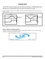
Page 11: ... For a filling application the ON setpoint must be less than the OFF setpoint See below NOTE For proper operation of the SP6R X controller the ON and OFF setpoints must not be set to the same value SJE 9 SP6R X Controller User Manual SP6R X POWER UP SCREEN VERSION On power up the screen will display the version of the program Always have the version number ready when contacting the factory for ser...

Page 12: ... SHIELD A OUT AO COM N C GND GND 1 2 3 4 5 6 7 8 9 10 11 12 J2 RELAYS 1 2 R1 3 4 R3 R4 R5 R6 5 6 7 8 9 10 11 12 R2 J3 INPUTS 1 2 3 4 5 6 7 8 9 10 11 12 13 14 15 16 GND SHIELD AI COM RESERVED RESERVED RESERVED RESERVED RESERVED RESERVED RESERVED AI LEVEL 24 VDC SUPPLY RESERVED RESERVED RESERVED RESERVED ...

Page 13: ...Y 1 2 3 R2 PROGRAMMABLE RELAY 2 4 5 R3 PROGRAMMABLE RELAY 3 6 7 R4 PROGRAMMABLE RELAY 4 8 9 R5 PROGRAMMABLE RELAY 5 10 11 R6 PROGRAMMABLE RELAY 6 12 J3 DIGITAL INPUTS PIN NAME DESCRIPTION 1 GND 2 RESERVED 3 RESERVED 4 RESERVED 5 RESERVED 6 RESERVED 7 RESERVED 8 RESERVED 9 RESERVED 10 RESERVED 11 RESERVED 12 RESERVED 13 SHIELD 14 AI COM 4 20 mALOOP RETURN 15 A INPUT 4 20 mALOOP INPUT 16 24 VDC OUT ...

Page 14: ...tion Codes Supported Read Holding Registers 0x03 Write Single Register 0x06 Write Multiple Registers 0x10 Anytime the SP6R X receives a valid Modbus request a Modbus Communication Active icon will appear on the Main Screen for 60 seconds If the Modbus master device is sending a Modbus request more often than once every 60 seconds the icon will effectively be displayed continuously To connect the S...

Page 15: ...42015 R6 Out of Range Behavior Read 2023 42024 0 Relay 1 Status 0 Relay Open 1 Relay Closed 1 Relay 2 Status 2 Relay 3 Status 3 Relay 4 Status 4 Relay 5 Status 5 Relay 6 Status 6 15 not used Read Write 2025 42026 Analog Input 4mA Tenths of Units Read Write 2026 42027 Analog Input 20mA Read Write 2027 42028 Transmitter Offset Read Write 2028 42029 Bar Graph Maximum Read Write 2029 42030 Bar Graph M...

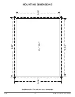
Page 16: ...SJE 14 SP6R X Controller User Manual MOUNTING DIMENSIONS Not to scale Do not use as a template T U O T U C 5 00 6 80 6 50 5 30 ...

Page 17: ...SJE 15 SP6R X Controller User Manual CONTROLLER DIMENSIONS 7 2 5 7 5 3 6 5 5 0 2 5 6 8 ESC SP6R X ...

Page 18: ...SJE 16 SP6R X Controller User Manual ELECTRICAL WIRING DIAGRAM ...

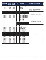
Page 19: ... 6 0 Relay 5 On 0 999 9 8 5 Relay 5 Off 0 999 9 8 0 Relay 6 On 0 999 9 9 5 Relay 6 Off 0 999 9 9 0 ANALOG SCALING SETTINGS Analog Input 4mA 0 999 9 0 0 Analog Input 20mA 0 999 9 10 0 Transmitter Offset 999 9 999 9 0 0 Analog Out Low Level 0 999 9 0 0 Analog Out High Level 0 999 9 10 0 Bar Graph Minimum 0 999 9 0 0 Bar Graph Maximum 0 999 9 10 0 Units List ft OUT OF RANGE BEHAVIOR SETTINGS Relay 1 ...

Page 20: ... 2020 SJE Inc All Rights Reserved PN 1066129B 11 20 Manufactured by SJE Inc Technical support 1 800 746 6287 techsupport sjeinc com www csicontrols com www primexcontrols com www sjerhombus com ...

Reviews: