background image

VFDC-3000

CONSTANT PRESSURE CONTROLLER

User Manual

PUMP 1

PUMP 2

PUMP 3

ALARM

ESC

PRESS FOR ENTER

P1

P2

P3

Summary of Contents for VFDC-3000

Page 1: ...VFDC 3000 CONSTANT PRESSURE CONTROLLER User Manual PUMP 1 PUMP 2 PUMP 3 ALARM ESC PRESS FOR ENTER P1 P2 P3 ...

Page 2: ...Interface 3 Main Menu 4 Controller Setpoints List 5 Basic Settings 6 Pump Settings 8 Advanced Settings 9 Controller Operation 11 Alarms 13 VFD and I O Status Screens 14 I O Table 15 Mounting Dimensions 16 Controller Dimensions 17 Electrical Wiring Diagram 18 SJE VFDC 3000 Controller User Manual ...

Page 3: ...n hazardous locations as defined by National Electrical Code ANSI NFPA 70 Do not connect power to this equipment if it has been damaged or has any missing parts Do not install in areas with excessive or conductive dust corrosive or flammable gas moisture or rain excessive heat regular impact shocks or excessive vibration SJE 1 VFDC 3000 Controller User Manual Warning Users must read this manual an...

Page 4: ...g 4 20mA pressure transmitter Rotary selector for menu navigation 2 7 blue OLED 64 x 256 pixel display DIMENSIONS 7 2 x 5 3 x 2 0 inches 18 3 x 13 5 x 5 1 cm PUMP CONTROL AND PROTECTION Automatic pump sequencing Multiple sequencing configurations Automatic pump sequencing on VFD fault Pump run indication Variable speed SYSTEM Alarm counts Number of starts for each pump Run time for each pump ELECT...

Page 5: ...ings Red LED Indicates an Active Alarm Green LED Indicates PUMP 1 Running Green LED Indicates PUMP 2 Running Green LED Indicates PUMP 3 Running button returns to previous menu screen and exits a parameter edit screen without saving changes ESC Left Shift Button for shifting the curser left and changing Value Adjustment Scale PUMP 1 PUMP 2 PUMP 3 ALARM ESC PRESS FOR ENTER P1 P2 P3 Lead pump indicat...

Page 6: ...ect any digit desired then press the ENTER button to save the setting or press ESC to leave the setting without saving The ESC button can be used to back out of any menu to the Main Display Counts and ETMs Elapsed Time Meters The following screen displays the nine different Counts and ETMs that are tracked A CLEARING COUNT APPROVAL screen can be viewed by clicking the ENTER button when the desired...

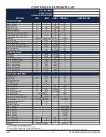
Page 7: ...ps 0 0 999 9 Amps 3 Pump 2 Motor Voltage 0 0 999 9 Volts 3 Pump 3 Overload Amps 0 0 999 9 Amps 3 Pump 3 Motor Voltage 0 0 999 9 Volts 3 ADVANCED SETTINGS Sensor Range 1 0 999 9 PSI 200 0 Sensor Offset 999 9 999 9 PSI 0 0 PID Proportional Term 0 999 70 PID Integral Term 0 999 35 PID Derivative Term 0 999 1 Setpoint Pressure 2 0 0 1 PSI 40 0 Pipe Fill Frequency 0 0 2 Hz 30 0 Pipe Fill Time 0 0 999 9...

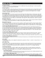
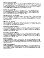
Page 8: ...stem pressure The lead pump will start if the pressure drops below the Setpoint Pressure less the Lead Pump Start Differential Pressure Example If the Setpoint Pressure is 40 PSI and the Lead Pump Start Differential Pressure is 5 PSI the lead pump will start when the pressure drops below 35 PSI Lag Pump Start Differential Pressure The Lag Pump Start Differential Pressure is the amount of pressure ...

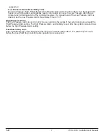
Page 9: ...l reset of the Low Pressure Alarm is desired set the Low Pressure Alarm Reset Delay Time to 0 0 High Pressure Alarm The High Pressure Alarm is used to notify the user and stop the pumps if the system pressure exceeds the High Pressure Alarm setting The High Pressure Alarm automatically resets after the system pressure drops below the High Pressure Alarm setting Low Water Delay Time The Low Water D...

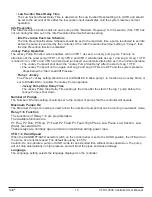
Page 10: ...n This is typically used on submersible type pumps where the manufacturer requires a faster acceleration rate from a stop to the Thrust Bearing Frequency for proper thrust bearing operation Set to 0 0 to disable the thrust bearing function Note If the Pipe Fill function is used at a lower frequency it will take precedence over the thrust bearing function Thrust Bearing Acceleration Set the Thrust ...

Page 11: ... adjusted by advanced users only Setpoint Pressure 2 The Setpoint Pressure 2 is the target pressure to be maintained at the pump discharge when the Setpoint Pressure 2 input is active on the controller The setting cannot exceed the maximum range of the pressure transmitter Pipe Fill Function The Pipe Fill function is used to limit the maximum speed of the Lead VFD on startup to less than or equal ...

Page 12: ... VFDs are OFF and the system pressure drops below the Start Lead diff Pressure Pump 1 Jockey The Pump 1 Jockey setting should be set to ENABLED to allow pump 1 to function as a Jockey Pump or set to DISABLED to not allow the Jockey Pump operation Jockey Pump Stop Delay Time The Jockey Pump Stop Delay Time setting is the time after the start of the lag 1 pump before the Jockey Pump is shut down Num...

Page 13: ...lls below the Sleep Frequency for the Sleep Delay Time the lead pump s operation shall be suspended Normal Operation Three Pumps Needed The lead pump starts when system pressure drops the Start Lead Differential Pressure below the Setpoint Pressure The lead pump runs and its speed is controlled via PID control If the lead pump running at the Maximum Frequency cannot keep up with the demand for wat...

Page 14: ...ly stop and a Low Water Alarm flag shall be set When the Low Water Alarm input deactivates the Low Water Alarm flag shall cease and normal operation shall resume Pressure Sensor Open Circuit Alarm At any time during operation if the controller senses an open circuit on the pressure transmitter all pump operation shall immediately stop and a Pressure Sensor Open Circuit Alarm flag shall be set When...

Page 15: ...the pressure transmitter input Check pressure transmitter cable check pressure transmitter connector replace defective pressure transmitter PUMP 1 FAULT There is an active fault condition on the pump 1 VFD Check active fault of pump 1 VFD repair fault condition of pump 1 VFD PUMP 2 FAULT There is an active fault condition on the pump 2 VFD Check active fault of pump 2 VFD repair fault condition of...

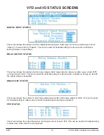
Page 16: ... of all six relay outputs Each relay output is shown as either open circuit Off or closed circuit On This can be used for troubleshooting to make sure the controller is turning on and off the output relays as expected ANALOG I O STATUS This screen shows the current in mA of the analog input A IN and analog output A OUT This can be used for troubleshooting to make sure the 4 20mA signals are behavi...

Page 17: ...9 RELAY 5 CONFIGURABLE RELAY 5 10 11 RELAY 6 CONFIGURABLE RELAY 6 12 J3 DIGITAL ANALOG INPUTS PIN NAME DESCRIPTION 1 COM INPUT COMMON RETURN 2 LOW SUCTION LOW SUCTION INPUT 3 HIGHPRESSURE HIGH PRESSURE INPUT 4 LOW WATER LOW WATER INPUT 5 SETPOINT 2 SETPOINT PRESSURE 2 INPUT 6 N C NO CONNECTION 7 N C NO CONNECTION 8 N C NO CONNECTION 9 N C NO CONNECTION 10 N C NO CONNECTION 11 N C NO CONNECTION 12 ...

Page 18: ...SJE 16 VFDC 3000 Controller User Manual MOUNTING DIMENSIONS Not to scale Do not use as a template T U O T U C 6 80 5 30 6 50 5 00 ...

Page 19: ...SJE 17 VFDC 3000 Controller User Manual CONTROLLER DIMENSIONS 7 2 5 7 5 3 PUMP 1 PUMP 2 PUMP 3 ALARM ESC PRESS FOR ENTER 6 5 5 0 2 5 6 8 P1 P2 P3 ...

Page 20: ...al ELECTRICAL WIRING DIAGRAM 1 2 3 4 5 6 7 8 H O A XOO XOX 23 24 13 14 H O A XOO XOX 23 24 13 14 H O A XOO XOX 23 24 13 14 1 2 3 4 5 6 7 8 9 10 11 12 1 2 3 4 5 1 2 3 G TB1 TB2 TB2 TB2 TB3 PRESSURE SENSOR 4 20mA LOW SUCTION PRESSURE SWITCH ...

Page 21: ...__________________________________________ _____________________________________________________ _____________________________________________________ _____________________________________________________ _____________________________________________________ _____________________________________________________ _____________________________________________________ _________________________________...

Page 22: ...Manufactured by SJE Inc Technical support 1 800 746 6287 techsupport sjeinc com www csicontrols com www primexcontrols com www sjerhombus com 2020 SJE Inc All Rights Reserved PN 1061617A 5 20 ...

Page 23: ...VFDC 3000 CONTROLADOR DE PRESIÓN CONSTANTE Manual de Usuario BOMBA 1 BOMBA 2 BOMBA 3 ALARMA ESC PRESIONE PARA GUARDAR B1 B2 B3 ...

Page 24: ...ciones establecidas del controlador 5 Configuración básica 6 Configuración de bombas 8 Configuración avanzada 9 Operación del controlador 11 Alarmas 13 Pantallas de estado VFD y E S I O 14 Tabla de Entradas Salidas E S I O 15 Dimensiones del montaje 16 Dimensiones del controlador 17 Diagrama de cableado eléctrico 18 SJE Manual de Usuario Controlador VFDC 3000 ...

Page 25: ...digo Eléctrico Nacional de Estados Unidos ANSI NFPA 70 NO conecte la corriente a este equipo si está dañado o le faltan piezas NO lo instale en áreas con excesiva presencia de polvo y o polvos conductores gas corrosivo o inflamable en condiciones de humedad o lluvia calor excesivo impactos constantes o vibración excesiva SJE 1 Manual de Usuario Controlador VFDC 3000 Advertencia los usuarios deben ...

Page 26: ... OLED azul de 64 x 256 píxeles y 6 9 cm 2 7 DIMENSIONES 18 3 x 13 5 x 5 1 cm 7 2 x 5 3 x 2 0 pulgadas CONTROL Y PROTECCIÓN DE LAS BOMBAS Secuencia automática de las bombas Múltiples configuraciones de secuencia Secuencia automática de bombas ante un fallo en los VFD s Indicación de bombas en funcionamiento Velocidad variable SISTEMA Contador de alarmas Número de arranques de cada bomba Tiempo de o...

Page 27: ...ire el botón para desplazarse por los menús o ajustar los parámetros Presione el botón ENTER para guardar los ajustes realizados LED rojo indica una alarma activa LED verde indica BOMBA 1 en operación LED verde indica BOMBA 2 en operación LED verde indica BOMBA 3 en operación El botón ESC retorna a la pantalla del menú anterior y sale de la pantalla de edición de parámetros sin guardar los cambios...

Page 28: ...go pulse ENTER para guardar la configuración o pulse ESC para salir de esa configuración sin guardarla El botón ESC puede usarse para salir de cualquier menú y retornar a la pantalla principal Contadores y ETM Medidores de Tiempo Transcurrido La pantalla siguiente visualiza los nueve Contadores y ETM que pueden visualizarse Para ver la pantalla APROBACIÓN PARA BORRAR CONTADOR haga clic en la tecla...

Page 29: ...s 0 0 999 9 Amperios 3 Voltaje Motor Bomba 2 0 0 999 9 Voltios 3 Sobrecarga Bomba 3 en amperios 0 0 999 9 Amperios 3 Voltaje Motor Bomba 3 0 0 999 9 Voltios 3 CONFIGURACIÓN AVANZADA Rango del sensor 1 0 999 9 PSI 200 0 Compensación del sensor 999 9 999 9 PSI 0 0 Término proporcional PID 0 999 70 Término integral PID 0 999 35 Término derivado PID 0 999 1 Presión establecida 2 0 0 1 PSI 40 0 Frecuen...

Page 30: ...Hz puede dañar la bomba Comuníquese con el fabricante de la bomba y del motor si se van a operar por encima de la frecuencia nominal indicada en la placa del motor Presión diferencial de arranque de la bomba principal La Presión diferencial de arranque de la bomba principal es la cantidad de caída de presión con respecto a la Presión establecida a la cual el VFD principal va a despertar del modo d...

Page 31: ... para reiniciar alarma de baja presión La configuración del Tiempo RET para reiniciar la alarma de baja presión debe corresponder a un tiempo posterior al valor configurado para un indicador de Alarma de baja presión hasta el reinicio automático del sistema Una vez efectuado el reinicio automático queda borrado el indicador de Alarma de baja presión y reanuda el funcionamiento normal del controlad...

Page 32: ... tasa de aceleración desde el punto donde la bomba está detenida hasta la Frecuencia del cojinete de empuje para el buen funcionamiento del cojinete Ajuste el valor a 0 0 para desactivar la función del cojinete de empuje Nota si se usa la función de llenado de la tubería Pipe Fill a una frecuencia menor va a tener prioridad sobre la función del cojinete de empuje Aceleración del cojinete de empuje...

Page 33: ... ajustado por usuarios avanzados exclusivamente Presión establecida 2 La Presión establecida 2 es el valor de la presión que se debe mantener en la descarga de la bomba cuando la entrada de la Presión establecida 2 está activa en el controlador El valor no puede exceder el rango máximo del transmisor de presión Función de Llenado de tubería La función de Llenado de tubería se utiliza para limitar ...

Page 34: ...eración normal La Bomba Jockey apaga el Retraso en la parada de la bomba Jockey después de que arranque el VFD de Reserva 1 La Bomba Jockey no vuelve a operar hasta que los VFD de Reserva 2 y Reserva 3 estén apagados OFF y la presión del sistema descienda por debajo de la Presión diferencial de arranque de la bomba principal Bomba 1 Jockey La Bomba 1 Jockey debe ajustarse a la posición ACTIVADA pa...

Page 35: ...stema excede la Presión diferencial de parada de la bomba de reserva por encima de la Presión establecida y si la Bomba 1 de reserva está operando a la Frecuencia mínima la salida de la Bomba 1 de reserva queda suspendida y se regula la velocidad de la bomba principal a través del control de la bomba principal Operación normal requiere tres bombas La bomba principal arranca cuando la presión del s...

Page 36: ...peraciones de la bomba cesan de inmediato y se activa un indicador de Alarma de bajo nivel de agua Al desactivarse la entrada de la Alarma de bajo nivel de agua el indicador de Alarma de bajo nivel de agua se cancela y se reanuda la operación normal Alarma de circuito abierto en el sensor de presión Si en cualquier momento durante la operación el controlador detecta un circuito abierto en el trans...

Page 37: ...ocircuito en la entrada del transmisor de presión Revise el cable del transmisor de presión y el conector del transmisor de presión remplace el transmisor de presión defectuoso FALLA BOMBA 1 Hay un estado de falla activa en el VFD de la Bomba 1 Revise la falla activa del VFD de la Bomba 1 repare la condición de fallo del VDF de la Bomba 1 FALLA BOMBA 2 Hay un estado de falla activa en el VFD de la...

Page 38: ...idas de relé Cada salida de relé se ilustra como un circuito abierto Apagado o cerrado Prendido Esto se puede usar en la localización de problemas para confir mar si el controlador está encendiendo y apagando las salidas de relé como es de esperarse ESTADO DE LAS E S ANALÓGICAS Esta pantalla muestra la corriente en mA para la entrada y salida analógicas Esto es útil en la localización de problemas...

Page 39: ...5 RELÉ CONFIGURABLE 5 10 11 RELÉ 6 RELÉ CONFIGURABLE 6 12 J2 ENTRADAS DIGITALES PIN NOMBRE DESCRIPCIÓN 1 COM ENTRADA RETORNO COMÚN 2 BAJA SUCCIÓN ENTRADA BAJA SUCCIÓN 3 ALTA PRESIÓN ENTRADA ALTA PRESIÓN 4 NIVEL BAJO DE AGUA ENTRADA NIVEL BAJO DE AGUA 5 VALOR ESTABLECIDO 2 ENTRADA PRESIÓN ESTABLECIDA 2 6 N C NO HAY CONEXIÓN 7 N C NO HAY CONEXIÓN 8 N C NO HAY CONEXIÓN 9 N C NO HAY CONEXIÓN 10 N C NO...

Page 40: ...SJE 16 Manual de Usuario Controlador VFDC 3000 DIMENSIONES DEL MONTAJE No están a escala No usar como plantilla CORTE 6 80 5 30 6 50 5 00 12 70 cm 13 46 cm 17 27 cm 16 51 cm ...

Page 41: ...00 DIMENSIONES DEL CONTROLADOR 7 2 5 7 5 3 BOMBA 1 BOMBA 2 BOMBA 3 ALARMA ESC 6 5 5 0 2 5 6 8 B1 B2 B3 6 35 cm 12 70 cm 14 48 cm 13 46 cm PRESIONE PARA GUARDAR 18 29 cm 17 27 cm 16 51 cm ALARMA BOMBA1 BOMBA2 BOMBA3 PRESIONE PARA GUARDAR B1 B2 B3 ...

Page 42: ...2A FUSIBLECLASECC 1 2A FUSIBLECLASECC 1 2A XF X1 H4 H3 H2 H1 480V 115V X2 GRD TERMOSTATO VENTILADOR ALIMENTACIÓN DE24VCC VARIADOR DE FRECUENCIA VARIADOR D700 BOMBA 3 BOMBA 3 BOMBA 2 BOMBA 2 VARIADOR D700 VARIADOR DE FRECUENCIA VARIADOR DE FRECUENCIA BOMBA 1 BOMBA 1 VARIADOR D700 ROJO NEGRO DE PRESIÓN DE PRESIÓN VALOR ESTABLECIDO 2 BAJO NIVEL DE AGUA ALTA PRESIÓN BAJA SUCCIÓN TIERRA TIERRA SALIDAAN...

Page 43: ...______________________________________________ _____________________________________________________ _____________________________________________________ _____________________________________________________ _____________________________________________________ _____________________________________________________ _____________________________________________________ _____________________________...

Page 44: ...Fabricado por SJE Inc Soporte técnico 1 800 746 6287 techsupport sjeinc com www csicontrols com www primexcontrols com www sjerhombus com 2020 SJE Inc Reservados todos los derechos PN 1061617A 5 20 ...

Reviews: