background image

チコーエアーテック株式会社

Copyright CHIKO AIRTEC CO., LTD. 2009

8

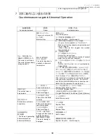
フィルタについて(フィルタ交換時期について参照)目詰まり状況をお知らせします。
(ホース圧迫や、ホース先端を絞込んだりした場合には、ランプが点灯し続ける場合があります)

Filter indicator lamps (Refer to “ Filter replacement timing”.) These lamps indicate the filter clogging status.
(A lamp may keep ON when the hose is pressed or when the hose end is compressed.)

正常(緑

LED

点灯):正常に運転しています

Normal lamp (green LED):Remains ON while the dust collector is operating normally.

確認(黄

LED

点灯):能力が低下していることをお知らせします。フィルタ・ダクトホース等を確認して下さい。

Cleaning lump(yellow LED)

Suction power is lowering. Check filter and duct hose.

交換(赤

LED

点灯):フィルタを交換してください。

Replacement lamp (red LED): Turns ON when replacement of the filter is necessary. Replace the filter.

異常お知らせについて

Error indicator lamps

過負荷(赤

LED

点灯):モータ異常が発生した時に赤

LED

ランプ点灯し、運転を停止します。

Overload lamp (red LED): Turns ON when an error occurs in the motor. The dust collector stops operation.

異常温度(赤

PL

点灯):モータが異常温度になった時に点灯、停止します。

Abnormal temperature lamp (red PL): Turns ON when the motor temperature becomes abnormal.
The dust collector stops operation.

原因除去後、リセットスイッチで復帰させ(ランプ消灯)、運転操作を開始してください。

After removing the cause of error, press the RESET switch. When the lamp turns OFF, restart the
operation.

主電源を切ることでも、ランプが消灯し、運転再開が可能です。

Or turn OFF the main power to turn OFF the lamp, and then restart the operation.

能力レベルについて

Performance level indicator

7

段階の

LED

により集塵機の吸込みを調整します。

Seven LED lamps indicate the suction level of the dust collector.

Lo

1

回押すごとに1レベル降下(最小約

60

%)

Lo switch: Every time this switch is pressed, the performance decreases by 1 level. (Minimum suction level:
Approximately 60%)

Hi

1

回押すごとに

1

レベル上昇(最大

100

%)

Hi switch: Every time this switch is pressed, the performance increases by 1 level. (Maximum suction level:
100%)

ON

/

OFF(タクトスイッチ)と主電源について

ON switch and OFF switch (tactile switches) and MAIN POWER indicator lamp

本体側面の主電源を入れると、ランプが点灯します。

MAIN POWER lamp: Turns ON when the MAIN POWER switch provided on the side of the main body is
turned ON.

ON

(緑

LED

点灯):起動 能力レベル設定可能

ON switch (with green LED): Starts up the dust collector, and enables setting of the performance level.

OFF

:運転停止

OFF switch: Stops operation of the dust collector.

(能力レベルは、OFF ボタンで記憶されますので、再スタートした時にはそのレベルで運転を開始します。
但し、運転中に能力レベルを変更し、停電などで主電源により電源 OFF した場合には、変更前のレベルで運転が開始さ
れます。)

(As the suction level is memorized by the OFF button, the operation starts in the same level at the time of
restart. However if the main power switch shut down by the blackout when suctionlevel is changed during the
operation, machine starts in suction level before the change.)

リセットスイッチ

RESET switch

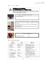
②の原因除去後、復帰する場合に使用します。先端の丸い棒などで、2秒間押して下さい。

Press and hold this switch with a thin rod having a round tip for 2 seconds to restore the dust collector after
removing the cause of error indicated by a lamp [2].

気圧の変化や温度条件により停止状態の圧力表示は-0.2kPa~0.2kPa の範囲で変化します。また、外部ノイズの影響によ
り一時的に圧力数値が変化する場合があります。

The pressure representation when operation stops changes within the range from -0.2 to 0.2.

Because there is a change in the atmospheric pressure and the temperature.
And the pressure representation might temporarily change because it is influenced by the extrinsic noise

.

※圧力数値

/ The pressure representation

フィルタランプ表示

/ Filter indicator lamps

Summary of Contents for SKV-250AT-ACC

Page 1: ...is instruction manual thoroughly and handle this SK Series machine correctly so that you can use it safely for a long time and enjoy its full performance Symbols used in this manual WARNING This symbo...

Page 2: ...osene paint etc Explosive dust Aluminum magnesium titanium zinc epoxy etc Dust containing sparks Dust containing sparks generated by high speed cutters grinders welding machines etc Fire sources Cigar...

Page 3: ...T AT panel 7 4 3 Remote connector 9 4 4 Confirmation before operation 9 4 5 Operation procedure 10 5 Remote Cable Sold Separately 11 5 1 Electrical circuit diagram 11 5 2 Remote Cable 11 5 3 Color and...

Page 4: ...y Do not install it outdoors 0 40 80 Install the product in a place without dew condensation at room temperature ambient temperature 0 to 40 C humidity 80 or less High temperature and dew condensation...

Page 5: ...repair 1 6 Disposal Dispose of the product properly as industrial waste 2 Confirmation and Preparation at Arrival After unpacking make sure that all parts are provided Contact our company immediately...

Page 6: ...e 1 Active carbon Colliding with granulated active carbon collects the particles passed through the primary filter and odor is removed carbon particle into the blower Main filter Collecting Adsorbing...

Page 7: ...When the filter replacement indicator lamp red turns ON replace the primary filter filter bag If the filter replacement indicator lamp does not turn OFF even after replacement of the primary filter f...

Page 8: ...eases by 1 level Minimum suction level Approximately 60 Hi 1 1 100 Hi switch Every time this switch is pressed the performance increases by 1 level Maximum suction level 100 ON switch and OFF switch t...

Page 9: ...ng plug are connected correctly insulation is provided properly and the rated voltage is realized Confirm items 1 to 3 above and then proceed to the item 4 AT Turn ON the MAIN POWER switch and confirm...

Page 10: ...nd confirm that the power indicator lamp lights Starts the dust collector AT ON Press the ON switch to start the operation 7 Choose operation ability in seven levels Push Lo switch or Hi switch in AT...

Page 11: ...panel and cause The wire 7 yellow is put inside a shrinkable tube so that it cannot be short circuited with other wires Remote operation switch ON Shifting to remote mode Remote control is possible in...

Page 12: ...ion The AT panel is disabled while the wires 4 and 8 are short circuited Yellow white Black White Operation pressure signal Output signals Transfers the current operation output Analog signal 0 5V Imp...

Page 13: ...Copyright CHIKO AIRTEC CO LTD 2009 13...

Page 14: ...in body Transfer required output signals in accordance with the explanation in 5 3 Color and signal of each wire AT ON Lo Hi Change with Lo Hi switch pushing the ON switch of main body AT panel when y...

Page 15: ...fore starting inspection Using a worn or damaged filter will release sucked dust to the atmosphere and damage electrical parts Make sure to inspect and maintain to prevent failures and accidents in th...

Page 16: ...make sure to attach it vertically If the nipple is inserted diagonally the clogging indicator lamp may malfunction and turn ON 1 Release the snap locks of the filter case and remove the primary filter...

Page 17: ...ds generated Is the installation level correct Filter installation status Once month Are the filters installed securely Filter clogged status Suction force check During operation Does the suction hose...

Page 18: ...verheated by clogged filters 3 30 After checking 1 to 3 above remove the cause of error and press the RESET switch Or turn OFF and ON the MAIN POWER switch to reset the error status Start the operatio...

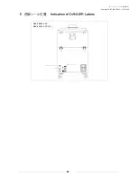
Page 19: ...Copyright CHIKO AIRTEC CO LTD 2009 19 8 Indication of DANGER Labels SKV 250AT ACC SKV 450AT ACC V1...

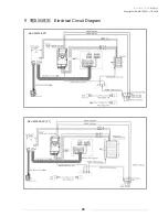
Page 20: ...Copyright CHIKO AIRTEC CO LTD 2009 20 9 Electrical Circuit Diagram SKV 250AT ACC SKV 450AT ACC V1...

Page 21: ...7 2 35 58 70 62 5 1 dB Note The Noise column indicates a value dB on the scale A at 1 m on the main body side when the hose is connected to the suction port 11 Consumable Parts List Model 1 Primary f...

Page 22: ...ubject to change without prior notice Memo about purchase Model Manufacturer s serial number Date of purchase Start of operation Your name Address Phone Person in charge LTD 562 0012 1 1 33 1 1 33 Hak...

Reviews: