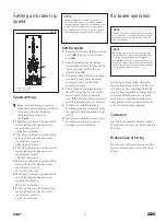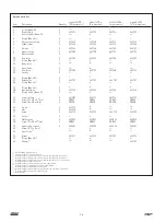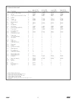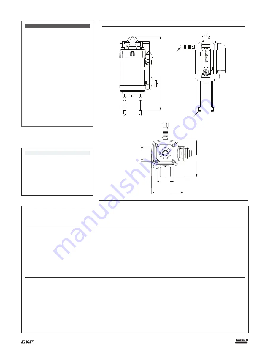
Specifications
Model
Cylinder
diameter
Effective
piston area
Operating pressure
range
Operating
temperature range
Minimum I D
of air supply
Air
Inlet
Air cons at
100 psi (7 bar)
94910 10 in
(254 mm)
78 in
3
(506 cm
3
)
50–100 psi
(3,4–7 bar)
–30 to 150 °F
(–34 to 66 °C)
3
/
4
in
(20 mm)
3
/
4
in NPTF
3 6 scf/cycle
(103 L(N)/cycle)
94908 8 in (203 mm)
50 in
3
(324 cm
3
)
50–100 psi
(3,4–7 bar)
–30 to 150 °F
(–34 to 66 °C)
3
/
4
in
(20 mm)
3
/
4
in NPTF
2 6 scf/cycle
(75 L(N)/cycle)
94906 6 in (152 mm)
28 in
3
(182 cm
3
)
40–100 psi
(2,7–7 bar)
–30 to 150 °F
(–34 to 66 °C)
1
/
2
in
(12 mm)
3
/
4
in NPTF
1 6 scf/cycle
(46 L(N)/cycle)
94904 4
1
/
4
in
(108 mm)
14 in
3
(92 cm
3
)
40–200 psi
(2,7–14 bar)
–30 to 150 °F
(–34 to 66 °C)
1
/
2
in
(12 mm)
1
/
2
in NPTF
1 1 scf/cycle
(32 L(N)/cycle)
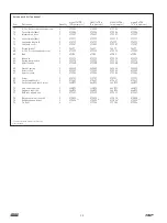
Model
Maximum
recomended speed
Effective
piston area
Weight
Seals
material
Dimension “A”
Dimension “B”
Dimension “C”
94910 75 cpm
1)
6 in
(152 mm)
62 lbs
(28,1 kg)
Buna-N and
Teflon
2)
13
1
/
4
in
(337 mm)
13
1
/
16
in
(332 mm)
22
3
/
4
in
(577 mm)
94908 75 cpm
1)
6 in
(152 mm)
47 lbs
(21,2 kg)
Buna-N and
Teflon
2)
11
1
/
4
in
(286 mm)
11 in
(279 mm)
22
3
/
4
in
(577 mm)
94906 75 cpm
1)
6 in
(152 mm)
34 lbs
(15,5 kg)
Buna-N and
Teflon
2)
9
1
/
4
in
(235 mm)
10
11
/
16
in
(271 mm)
22
3
/
4
in
(577 mm)
94904 75 cpm
1)
6 in
(152 mm)
25 lbs
(11,7 kg)
Buna-N and
Teflon
2)
7
1
/
2
in
(191 mm)
8
11
/
16
in
(221 mm)
23
5
/
8
in
(599 mm)
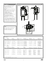
C
1)
/ -20
1
2
4 in
(101 mm)
4 in
(101 mm)
B
A
WARNING
Do not exceed stated maximum working
pressure of air motor or lowest rated
component in your system
Do not
alter or modify any part of
equipment
Do not
operate equipment with combus-
tible gas
Do not
attempt to repair or disassemble
equipment while system is pressurized
Tighten
all fluid connections securely
before using equipment
Always
read and follow fluid
manufacturer’s recommendations
regarding fluid compatibility, and use of pro-
tective clothing and equipment
Check
all equipment regularly and
repair or replace worn or damaged parts
immediately
Failure to heed warnings including misuse,
over pressurizing, modifying parts, using
incompatible chemicals and fluids, or using
worn or damaged parts, may result in seri-
ous personal injury and/or damage to equip-
ment, fire, explosion, or property damage
1)
Air inlet
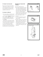
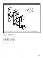
Fig. 1
Dimensions
1)
0 45 cpm with air brake engaged
2)
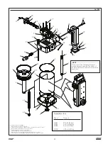
Teflon seals used with power valve spool (
13
) and relay valve (
17
)
NOTE
Do not operate with air contaminated with
materials that are not compatible with
Buna-N seals Use only with
6 in (
152 mm
) stroke pump tubes
3

