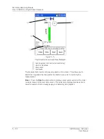
The Analyzer Module
Ho
w to Perform a Bump Test
How to Perform a Bump Test
Overview
Warning - Due to required accessories, this module is not for use in Class I
Division 2 hazardous locations. Restrictions apply when used in ATEX zone 2
hazardous locations. Reference this manual's Appendix D, Safety Instructions for
details.
A
bump test
(also called a
hammer test
) determines the natural frequencies of a
machine or a structure. The idea behind the test is that when an object is impacted or
“bumped,” the object's natural or resonant frequencies are excited. If a spectrum is
taken while the object is vibrating due to the impact, spectral peaks result, pinpointing
the object's natural frequencies. A Microlog analyzer can be used to capture this
vibration response and to display a spectrum showing the resonant or natural
frequencies.
Why Do a Bump Test?
Vibration forces transmitted by rotating machines often excite natural resonances in
attached structures. Whenever such structural resonances appear, vibration responses
are amplified and can result in fatigue failures. Structural resonances can also mask
the cause of a machine's vibration, making it difficult to implement corrective machine
maintenance. Bump tests identify a structure's resonant modes and provide a
maintenance engineer the opportunity to change the resonance frequency so as to
reduce or eliminate damaging vibration.
To Perform a Bump Test
To Perform the Bump Test Using the Default Setup
•
Attach the accelerometer to the test object (machine case or structure).
•
From the
Analyzer
screen, use the arrow keys to highlight the
Bump Test
icon,
and press the
Start
function button. The measurement is performed and the initial
measurement results display.
If you highlight a measurement’s icon and press the Enter (Fire)
button instead of the
Start
function button, you will display the
measurement’s setup screen, not start the measurement.
SKF Microlog - GX Series
4 - 33
User Manual


