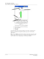
The Analyzer Module
How to Perform Motor Current Measurements
Bump Test Measurement Setup Fields
Bump test setup fields operate as previously described in the
Analyzer Measurement
Setup Fields
section. Reference this previous section for details.
Save
– If desired, from the measurement setup screen, you may press the
Save
function button to save the measurement setup for easy reuse in the future. Reference
Chapter 4, The Analyzer Module
section on
How to Save, View, and Delete Analyzer
Measurement Results
for detailed information on these procedures.
•
After you are finished with your measurement setup changes, press the
Start
function button to begin the measurement using the new settings. The
measurement is performed and the initial measurement results display.
•
Use cursor functions to analyze the measurement.
Average
,
Stop
,
Start
,
View
and
Save
function button options operate as previously
described in the
Using the Default Measurement Setup
section. Reference this
previous section for details.
How to Perform Motor Current Measurements
Overview
The Analyzer’s
Motor Current
option simplifies the process of analyzing and diagnosing
AC induction motor rotor bar defects. The Microlog’s Motor Current option acquires the
signal from an SKF CMAC 5208 current clamp and produces a very high definition
spectrum on its display. The analyst can then view the spectrum to differentiate
between the motor slip frequency and the electrical frequency and observe the
sidebands. Once these are measured, the operator needs to determine by calculat
ion
whether there is an indication of high resistance or broken rotor bars. The collected
motor current data resides in the Microlog.
The Microlog is a four channel analyzer, so you can use three
motor current clamps and look at all three phases simultaneously.
Warning - Due to required accessories, this module is not for use in Class I
Division 2 hazardous locations. Restrictions apply when used in ATEX zone 2
hazardous locations. Reference this manual's Appendix D, Safety Instructions for
details.
To Perform a Motor Current Test
To Perform the Motor Current Test Using the Default Setup
•
Connect the motor current clamp(s) to the monitored motor as required.
•
From the
Analyzer
screen, use the arrow keys to highlight the
Motor Current
icon,
and press the
Start
function button. The measurement is performed and the initial
measurement results display.
If you highlight a measurement’s icon and press the Enter / Fire
button instead of the
Start
function button, you will display the
measurement’s setup screen, not start the measurement.
4 - 36
SKF Microlog - GX Series
User Manual


