8
Frequency Response Function Module
Overview
Warning - Due to required accessories, this module is not for use in Class I
Division 2 hazardous locations. Restrictions apply when used in ATEX zone 2
hazardous locations. Reference this manual's Appendix D, Safety Instructions for
details.
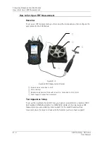
The Microlog FRF module allows the user to determine the natural frequencies of a
machine or structure in a more sophisticated manner than the Bump Test module.
Rather than simply detecting the frequencies where resonances occur, it captures
information about the Frequency Response Function of the structure being tested. The
FRF data can be used in conjunction with a Modal Analysis package to model the way
the structure will react to forces applied to it.
The FRF module can also be used to capture information about how a machine moves
when it is running. This information can be used in conjunction with Operation
Deflection Shape (ODS) analysis software.
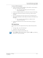
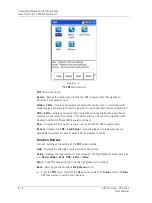
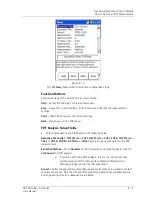
The FRF module includes features for ease of use, including:
•
Simple selection of measurement type from a list of predefined options (e.g.,
Mobility, Stiffness, Apparent Mass, etc.)
•
FRF trace colored green or red to illustrate high or low coherence
•
O
ptional automatic parameter setting for input ranges, number of lines, and
windowing
•
C
ompatibility with ODS analysis software
Additional Background Information
Newton’s Law and Apparent Mass
Newton’s Law states that force equals mass x acceleration; i.e.:
•
F = ma
Rearranging this gives:
•
m = F/a
The units for this are N/m/s
2
. The definition of a Newton:
•
N = kg x m/s
2
So we can see that:
•
N/m/s
2
= kg
SKF Microlog - GX Series
8 - 1
User Manual


