3. Design and function
page 13
EN
3.4 Design
An oil + air lubrication system can be subdivided
into areas for oil supply/oil metering and com-
pressed air supply. The oil can be metered and the
compressed air admixed either by an oil + air
metering unit (oil is metered and compressed air is
admixed in one component) or using separate
mixing valves that are combined with piston dis-
tributors, injection oilers or micropumps (oil is
metered and the compressed air is admixed in
separate components).
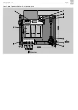
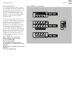
The basic design of an oil + air lubrication system
consists of the following components (Fig. 1):
)
Compact unit with or without control unit (Fig.
1 shows compact unit without control unit)
and with gear pump (1), lubricant reservoir
(2), the valve set required for pressure relief
and regulation, a pressure switch for electrical
monitoring of oil pressure build-up, a pres-
sure gauge (4) for visual monitoring of oil
pressure build-up, and a fill level switch for fill
level monitoring.
)
Pressure control valve with pressure gauge (6)
for compressed air control
)
Pressure switch (8) for monitoring of minimum
air pressure
)
Oil + air metering unit (9) for metering oil and
admixing compressed air
The components in the basic design are arranged
on a mounting plate and supplied as a complete oil
+ air lubrication system.
If necessary, additional components can optionally
be integrated into the oil + air lubrication system,
for example:
)
Oil filters (with or without electrical contamina-
tion monitoring)
)
Air filters (with or without electrical
contamination monitoring)
)
Additional pressure switches for lubricant and
compressed air monitoring
)
Flow sensors for monitoring lubricant trans-
port in lubrication lines
)
Flow sensors for monitoring lubricant trans-
port (oil streak) in lubrication point lines
For detailed information about the components
installed in a special oil + air lubrication system,
see the documentation of the oil + air lubrication
system.
If no documentation is available, you can
request the documentation directly from
SKF Lubrication Systems Germany
GmbH.
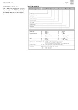
Summary of Contents for OLA Series
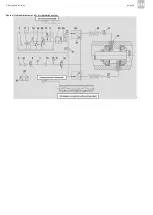
Page 19: ...3 Design and function page 19 EN Figure 4 Hydraulic diagram of oil air lubrication system ...
Page 49: ...blank page ...
Page 50: ...blank page ...
Page 51: ...blank page ...


