3. Design and function
page 14
EN
3.5 Description of components
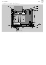
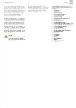
Figure 1 shows an oil + air lubrication system;
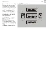
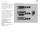
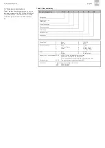
Figures 2 and 3 show the various oil + air metering
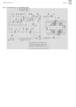
units. Figure 4 shows the hydraulic diagram of an
oil + air lubrication system.
Compact unit without control unit (1)
The compact unit without control unit (1) consists
of a gear pump, lubricant reservoir (2), the valve
set required for pressure relief and regulation, a
pressure switch for electrical monitoring of oil
pressure build-up in the main lubricant line, a
pressure gauge (4) for visual monitoring of oil
pressure build-up in the main lubricant line, and a
fill level switch for fill level monitoring.
Compact units are available in model designs with
or without a control unit. In the model design
without a control unit, the compact unit (and
thereby the lubrication interval) is controlled by the
control unit of the machine that the oil + air lubri-
cation system is mounted on. In the model design
with a control unit, the compact unit is equipped
with an electronic control unit that controls the
compact unit (and thereby the lubrication interval).
Details on the function and operation of the com-
pact unit and the electronic control unit can be
found in the assembly instructions for the compact
unit and the operating instructions for the elec-
tronic control unit which are included in the scope
of delivery of the oil + air lubrication system.
Compressed air control valve (6)
The compressed air control valve (6) is used to set
the air pressure of the compressed air fed to the oil
+ air metering unit and the lubrication point lines.
The compressed air transports the oil streak on the
inner wall of the lubrication point line, starting
from the oil + air metering unit, through the lubri-
cation point line and to the lubrication point. The
compressed air must be fed uniformly to ensure
constant transport of the oil streak, which ensures
constant lubricant supply to the lubrication point.
The air pressure is set manually and can be read
directly on the integrated pressure gauge (7) on
the compressed air control valve (6). An air filter
with an integrated water separator can optionally
be used.
Figure 1. Design of an electrically driven oil +
air lubrication system (schematic diagram,
subject to change)
1 Compact unit without control unit
2 Lubricant reservoir
3 Filler socket
4 Oil pressure gauge
5 Compressed air connection
6 Compressed air control valve
7 Pressure gauge for compressed air supply
8 Pressure switch for minimum air pressure
9 Oil + air metering unit
Summary of Contents for OLA Series
Page 19: ...3 Design and function page 19 EN Figure 4 Hydraulic diagram of oil air lubrication system ...
Page 49: ...blank page ...
Page 50: ...blank page ...
Page 51: ...blank page ...

