6. Operation
page 35
EN
6.2.1 Setting-up mode
The oil + air lubrication system must be brought
into service as described below in order to ensure
proper functioning:
MV20X-20 oil + air metering unit
)
Close the pressure control valve for com-
pressed air (item 6 in Fig. 1) to interrupt the
compressed air supply
)
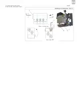
Remove screw plugs from the pressure gauge
connections (item 12 in Fig. 3) on the oil + air
metering unit (item 9 in Fig. 1).
)
Switch on the power supply and run the com-
pact unit until lubricant without bubbles is
discharged at the openings of the pressure
gauge connections.
)
Reinsert the screw plugs.
)
Open the pressure control valve for com-
pressed air (item 6 in Fig. 1) and set the
operating pressure (min. 3 - 10 bar, preferably
6 - 10 bar).
)
Run the compact unit until a continuous oil
streak has formed in the lubrication point lines
and fine lubricant droplets discharge at the
nozzles.
)
If necessary, adjust the air flow rate using the
air adjustment screws on the oil + air metering
unit (item 10 in Fig. 2 and 3) or the pressure
control valve for compressed air (item 6 in Fig.
1)
MV50X oil + air metering unit
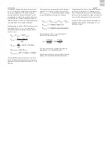
The oil + air metering units of the MV50X series
contain an externally mounted pressure-regulating
valve (item 16, Fig. 3) with a cracking pressure of
23 bar. The pressure-regulating valve is necessary
in order to ensure automatic venting of the main
lubricant line (supply of lubricant from compact unit
to oil + air metering unit) and the oil + air metering
unit.
The pressure-regulating valve is connected to the
compact unit's return connection via a return line to
feed discharged lubricant back into the lubricant
reservoir. Venting is performed automatically at the
start of each lubricating cycle (start-up of the
compact unit) and ensures bubble-free supply of
lubricant to the MV50X oil + air metering unit.
The air pressure must be set at a level sufficient to
deliver the compressed air volume in each lubrica-
tion point line, taking into account pressure losses
in the lubrication point line and the bearing assem-
bly. The available air pressure at the compressed
air inlet (connection to compressed air supply)
should be at least 3 bar, but preferably a minimum
of 6 bar.
Ensure that continuous oil streaks are formed in the
lubrication point lines.
6.3 Lubricant delivery to bearing
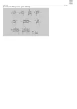
The way in which lubricant is delivered to the
bearing depends on the type of bearing and the
bearing assembly's design features. Figure 7 shows
recommended examples for lubricant delivery.
With single-row rolling bearings, the lubricant can
be introduced into the bearing from the side. The
nozzle should be located at the level of the inner
ring of the rolling bearing. The oil + air stream must
never be aimed directly at the rolling bearing's ball
cage.
With rolling bearings that exert pumping action in
one direction (e.g., angular contact bearings), the
lubricant must be fed in the direction of pumping
action.
The lubricant should be introduced into the bearing
assembly through a nozzle whose length depends
on the size of the bearing module. Suitable nozzles
can be ordered from SKF Lubrication Systems
Germany GmbH.
It is also possible to deliver the lubricant directly
into the outer ring of the rolling bearing through a
bore hole. In this case, ensure that the lubricant
does not feed into the rolling bearing's pressure
zone between the ball ring and outer ring (Fig. 6).
Summary of Contents for OLA Series
Page 19: ...3 Design and function page 19 EN Figure 4 Hydraulic diagram of oil air lubrication system ...
Page 49: ...blank page ...
Page 50: ...blank page ...
Page 51: ...blank page ...

