


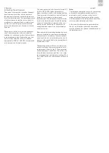


6. Operation
page 36
EN
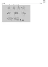
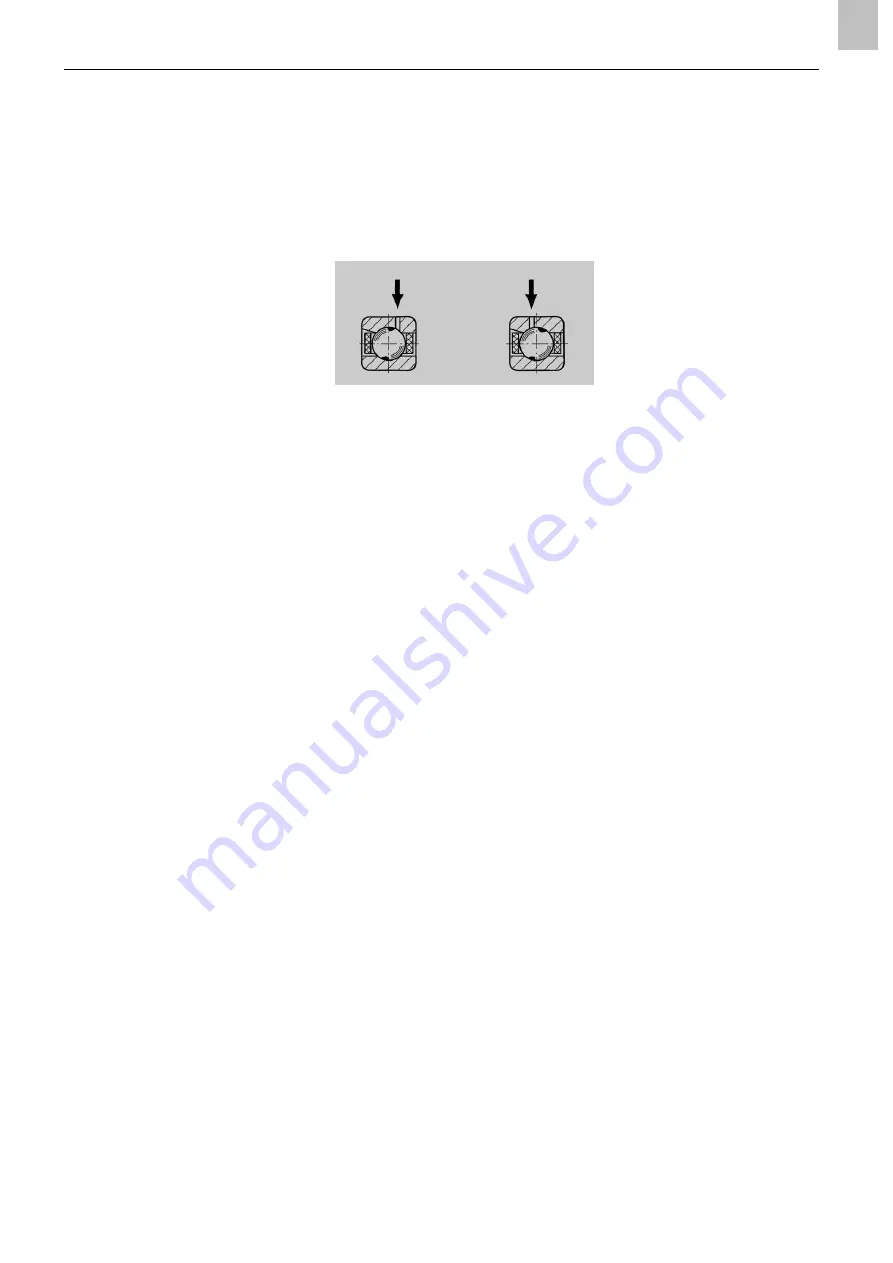
With double-row cylindrical roller bearings, the
lubricant should be introduced into the rolling
bearing from the side at the level of the outer ring
raceway. The lubricant is then distributed almost
uniformly to both rows of bearings (Fig. 7).
With rolling bearings with an outer diameter of 150
to 280 mm, it is recommended that a second nozzle
be installed. In case of larger rolling-bearing outer
diameters, additional nozzles should be installed
accordingly.
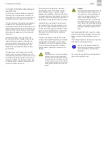
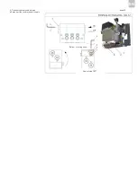
If the lubricant is fed through the outer ring of a
rolling bearing, a single nozzle is sufficient for most
applications.
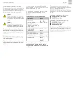
The air pressure indicated in Table 3 is generally
sufficient to reliably overcome the air vortex that
arises when using high-speed rolling bearings.
Higher air pressures needed to reliably feed lubri-
cant in individual cases do not impair the function of
the overall oil + air lubrication system.
The lubricant fed to the rolling bearing and the
entire bearing assembly must be drained to prevent
an oil sump from forming in the lower part of the
bearing assembly. For this purpose, it is advisable to
drill a drainage hole in the lower part of the bearing
assembly so the lubricant can flow out. As a rule of
thumb, the diameter of the drainage hole should be
six times the inlet cross-section, with a minimum
diameter of 5 mm.
Figure 6: Lubricant delivery through outer ring
Oil + air
Summary of Contents for OLA Series
Page 19: ...3 Design and function page 19 EN Figure 4 Hydraulic diagram of oil air lubrication system ...
Page 49: ...blank page ...
Page 50: ...blank page ...
Page 51: ...blank page ...


