background image

7. Shutdown 

page 43 

EN 


7. Shutdown 

7.1 Temporary shutdown 

You can temporarily shut down the described 
product by disconnecting the electrical, pneumatic, 
and/or hydraulic supply connections. For more 
information, see the section 'General information' in 
this installation instructions. 
 
If you wish to shut down the product temporarily, 
refer also to the instructions in the section 'Trans-
port, delivery, and storage' of this 

owner’s manual

 
When placing the product back into operation, refer 
to the information in the sections 'Installation' and 
'Startup

 of this 

owner’s manual


7.2 Permanent shutdown 

All country specific legal guidelines and legislation 
on the disposal of contaminated equipment must be 
observed when shutting down the product for the 
final time. 
 

Caution! 

Lubricants can contaminate the ground 
and watercourses. Lubricants must be 
used and disposed of properly. Country 
specific regulations and laws on the use 
and disposal of lubricants must be ob-
served. 

 
SKF Lubrication Systems Germany GmbH will take 
back the product and arrange for its legal disposal. 
Costs to the customer will be limited to SKF's 
incurred costs. 

Summary of Contents for OLA Series

Page 1: ...n and Maintenance Instructions Original installation instructions in accordance with EC Machinery Directive 2006 42 EC Version 05 WARNING Read this owner s manual before installing operating or maintaining the product Failure to follow the instructions and safety precautions in this owner s manual could result in serious injury death or property damage Keep for future reference ...

Page 2: ...hanical reproduction copying and distri bution of this documentation or parts thereof by means of processes such as data processing data carriers and data networks is strictly prohibited without the express permission of SKF Lubrication Systems Germany GmbH SKF Lubrication Systems Germany GmbH reserves the right to make content and technical changes Service If you have technical queries please con...

Page 3: ...iption of components 14 3 6 Function 20 3 7 Models and designations 21 4 Installation instructions 22 4 1 Positioning and mounting 22 4 2 Mounting dimensions 23 4 3 Electrical connection 23 4 3 1 Electrical connection motor 23 4 3 2 Inductive loads 24 4 4 Control and monitoring 25 4 4 1 Oil air lubrication systems without control unit 25 4 4 2 Oil air lubrication systems with control unit 26 4 5 C...

Page 4: ... s but does not contain any assurance of properties b The safety instructions in the owner s manual must be observed c The certified product must not be started up until it is confirmed that the equipment ma chinery vehicle or the like in which the product was installed meets the provisions and re quirements of the national directives to be ap plied This is in particular important for the implemen...

Page 5: ...eanings Read this Owner s Manual before installing oper ating or maintaining the product Failure to follow the instructions and safety precautions in this owner s manual could result in serious injury death or property damage Keep for future refe rence Note Not every symbol and corresponding infor mation described in the Safety Information is used in this owner s manual Information symbols Symbole...

Page 6: ...t and is intended for use in centralized lubrication systems Any other use of this product constitutes improper use Hazardous materials of any kind especially the materials classified as hazardous by CLP Regulation EC 1272 2008 may only be used to fill SKF centralized lubrication systems and components and deliv ered and or distributed with the same after consulting with and receiving written appr...

Page 7: ...when they are being oper ated Such systems must therefore be depressurized before starting installa tion maintenance or repair work and before making any changes to the sys tem 1 5 Danger relating to compressed air Danger The described product may be under pressure when it is being operated The product must therefore be depressur ized before starting installation mainte nance or repair work and be...

Page 8: ...approved for use in conjunction with gases liquefied gases gases dissolved under pressure vapours and fluids with a vapour pressure of more than 0 5 bar above normal atmospheric pressure 1013 mbar at the maximum permitted temperature Should there be a need to use the product to convey media other than lubricants or hazardous substances this must be discussed with SKF Lubrication Systems Germany Gm...

Page 9: ...nancial economic aspects must also be consid ered If required SKF Lubrication Systems Germany GmbH can help customers to select suitable components for the con veyance of the selected lubricant and to plan and design their centralized lubri cation system If you have further questions you can contact SKF Lubrication Systems Germany GmbH We can test lubricants in our own laboratory to establish thei...

Page 10: ...which may reduce bearing service life Oils with solid additives cannot be used as such oils may leave solid particle sediment within the oil circuit and thereby block the circuit s function There is also a risk of solid particles creating a coating that critically reduces the bearing clear ance Table 1 Permitted oils 2 4 Lubricants and the environment Caution Lubricants can contaminate the ground ...

Page 11: ... system or components of the lubrication equip ment have to be sealed immediately Leaking centralized lubrication systems or compo nents of the lubrication equipment are a source of danger in relation to slip hazard and the risk of injury These dangers can cause physical injury to persons or damage to other material assets Lubricants are hazardous substance Refer to safety precautions in the lubri...

Page 12: ...he air stream to the attached lubrication point line A nearly continuous oil flow is generated by a lubrication point line that is at least 1 m long between the metering device and the entrance to the lubrication point This oil flow exits the lubrica tion point line as fine oil droplets and is fed to the lubrication point The oil droplets fed to the lubri cation point lubricate the friction partne...

Page 13: ...nd a fill level switch for fill level monitoring Pressure control valve with pressure gauge 6 for compressed air control Pressure switch 8 for monitoring of minimum air pressure Oil air metering unit 9 for metering oil and admixing compressed air The components in the basic design are arranged on a mounting plate and supplied as a complete oil air lubrication system If necessary additional compone...

Page 14: ... unit and the electronic control unit can be found in the assembly instructions for the compact unit and the operating instructions for the elec tronic control unit which are included in the scope of delivery of the oil air lubrication system Compressed air control valve 6 The compressed air control valve 6 is used to set the air pressure of the compressed air fed to the oil air metering unit and ...

Page 15: ...3 Design and function page 15 EN Air Oil Oil and air Figure 1 Design of an electrically driven oil air lubrication system ...

Page 16: ...um air pressure must be monitored as insufficient com pressed air supply carries a risk of underlubricating the lubrication point because the lubricant in the lubrication point lines is no longer reliably trans ported to the lubrication point Figure 2 MV20X 20 oil air metering unit AIR AIR OIL OIL 9 10 11 15 12 13 13 15 14 14 Figure 2 MV20X 20 oil air metering unit schematic diagram subject to cha...

Page 17: ... be connected in series if more lubrication line connections are required In the oil air metering unit the lubricant is separately metered for each lubrication point and transported by the air stream into the lubrication point line and through to the lubrication point The air stream required for each lubrication point can be set individually using the air regulating screws in the oil air metering ...

Page 18: ...icant line connection of the oil air metering unit Caution On oil air metering units of the MV50X series only one pressure regulating valve 23 bar can be installed after the last metering point Oil air metering units of series MV50X and MV20X 20 can be combined and utilized together in an oil air lubrication system This allows the system to cover the entire potential metering range from 2 mm to 16...

Page 19: ...3 Design and function page 19 EN Figure 4 Hydraulic diagram of oil air lubrication system ...

Page 20: ...ing cham bers in the oil air metering unit are completely emptied A delay time of 5 seconds is recom mended other times are possible based on the layout of the oil air lubrication system The operating pressure built up during the lubricating cycle is monitored by the electrical pressure switches installed in the compact unit If present the operating pressure is also monitored visually by a pressur...

Page 21: ...lter design Design number Voltage key Control unit 0 None 5 IG54 20 2 IG38 30 9 Other Reservoir capacity 0 None 3 3 liters 1 Less than 2 liters 6 6 liters plastic 2 2 liters 7 6 liters metal 8 6 liters metal Filter 0 None 2 Air filter 1 Oil filter 3 Oil and air filter Number of oil air connections 01 30 MV20X 20 max 8 lubrication line connections MV50X max 6 lubrication line connections Oil air me...

Page 22: ...Oil air lubrication systems must not be tipped up or dropped Country specific accident prevention regulations and the operating and maintenance instructions of the operator must be observed when carrying out all installation work on machineries 4 1 Positioning and mounting Oil air lubrication systems should be mounted in a way that protects it from humidity and vibrations It should also be easily ...

Page 23: ... of the fixing holes see the documentation of the oil air lubrication system If no documentation is available the di mensions and location of the fixing holes for mounting the unit can be determined by taking measurements If no documentation is available you can directly request the documentation from SKF Lubrication Systems Germany GmbH 4 3 Electrical connection 4 3 1 Electrical connection motor ...

Page 24: ...ocumentation directly from SKF Lubrication Systems Germany GmbH The electrical circuit diagram of the compact unit is affixed inside the unit s cover cap and can be accessed by removing the cap This diagram is affixed in such a way that it cannot be removed 4 3 2 Inductive loads In the case of switches with inductive loads they must be low inductive in order to keep wear on contact areas to a mini...

Page 25: ...ing cycle consists of the contact time and the interval time Operating mode S3 for the gear pump motor is used to define the interval time and the gear pump s cycle time and delay time Consult the documentation of the oil air lubrication system for information about this operating mode The following are monitored Pressure build up in the main lubricant line oil pressure build up Minimum air pressu...

Page 26: ... running The pump cycle time is 60 seconds and cannot be adjusted The electrical connection of the monitoring units is established at the terminal strip of the compact unit s electronic control unit The control unit directly monitors the operation of the oil pressure switch air pressure switch and fill level switch Oil air lubrication systems with an electronic control unit are supplied with all i...

Page 27: ... must comply with at least quality class 3 as defined by DIN ISO 8573 1 Table 3 Requirements for compressed air Compressed air preparation can be optimized and machine downtime and high maintenance costs avoided by using compressed air of the appropriate quality class The connection for the compressed air line is designed as an M10x1 pipe thread with a counter bore for a solderless pipe union per ...

Page 28: ...ings are required to install the lubrication point line Lubrication point line plastic tubing Ø 4 mm 404 603 Reinforcing socket 404 611 Tapered sleeve 404 612 Socket union The lubrication point lines can be laid in a rising or falling position A hose coil 30 is installed approx 0 3 m in front of the nozzle 32 and serves as a lubricant reservoir After the compressed air is switched off the lubrican...

Page 29: ...4 Installation instructions page 29 EN 9 1 10 m 30 32 Figure 5 Assembly structure for lubrication point line 9 Oil air metering unit 30 Hose coil 32 Nozzle ...

Page 30: ... to enter the lubrication line system Lubrication lines must be laid in a way that pre vents air pockets from forming anywhere on the system Cross section changes to the lubrication line from a small to a large cross section in the di rection of flow of the lubricant are to be avoided Transitions from one cross section to another should be smooth The flow of the lubricant in the lubrication lines ...

Page 31: ...Remove the screw plug 3 marked Oil on the opposite side of the main oil port Switch on the pump and allow it run until it pumps oil The oil now enters the mixing valve through the main oil port and discharges on the opposite side Allow the pump to run until oil without bubbles discharges Close the borehole on the main oil duct again with the screw plug 3 Shut off the pump Venting the metering unit...

Page 32: ...5 Transport delivery and storage page 32 EN Reconnect the compressed air supply Bottom of mixing valve View rotated 180 ...

Page 33: ...orage of lubrication units Ambient conditions Dry dust free environ ment storage in well ventilated dry area Storage time 24 months max Permitted air humidity 65 Warehouse temperature 10 40 C Light Direct sunlight UV radiation must be avoided nearby sources of heat must be screened 5 3 2 Storage of electronic and electrical devices Ambient conditions Dry dust free environ ment storage in well vent...

Page 34: ... without introducing bubbles Caution Different lubricants cannot be mixed as mixing may result in damage and ne cessitate costly and complicated cleaning of the compact unit the oil air lu brication system It is recommended that an indication of the lubricant in use be attached to the lubricant reservoir in order to prevent accidental mixing of lu bricants 6 2 Commissioning All electrical hydrauli...

Page 35: ...ricant back into the lubricant reservoir Venting is performed automatically at the start of each lubricating cycle start up of the compact unit and ensures bubble free supply of lubricant to the MV50X oil air metering unit The air pressure must be set at a level sufficient to deliver the compressed air volume in each lubrica tion point line taking into account pressure losses in the lubrication po...

Page 36: ...pplications The air pressure indicated in Table 3 is generally sufficient to reliably overcome the air vortex that arises when using high speed rolling bearings Higher air pressures needed to reliably feed lubri cant in individual cases do not impair the function of the overall oil air lubrication system The lubricant fed to the rolling bearing and the entire bearing assembly must be drained to pr...

Page 37: ...6 Operation page 37 EN Oil air Exhaust air Figure 7 Lubricant delivery on various types of ball bearings ...

Page 38: ...nificantly more lubricant than bearings without pumping action e g cylindrical roller bearings The amount of lubricant required by a bearing is generally specified by the bearing or machine manufacturer The amount of lubricant required is usually indicated in mm h if other units are used they must be converted accordingly See the following for information about configuring the oil air lubrication ...

Page 39: ...ched on as a percentage of the working cycle time TWC S3 pump cycle time incl pump delay time The time range of 1 25 to 25 min is the range of selectable working cycle times TWC S3 in minutes with It follows that On the basis of the calculated working cycle time TWC S3 these formulas can be used to determine the pump cycle time TPCT incl pump delay time TPDT and the interval time TINTERVAL ON time...

Page 40: ... minimum interval time TINTERVAL min 5 minutes rounded up yielding a minimum working cycle time of 6 minutes The maximum number of cycles per second is therefore 10 lubricating cycles This must be taken into consideration when de signing the oil air lubrication system The electronic control units are available in special designs with a programmable pump delay time Configuration of the interval tim...

Page 41: ...e losses in the lubrication point line and the bearing assembly The available air pressure at the com pressed air inlet connection to compressed air supply should be at least 3 bar but preferably a minimum of 6 bar When using high speed rolling bearings higher air pressure is required in order to overcome bearing back pressure air turbulence To ensure reliable operation of the oil air lubrication ...

Page 42: ...ble in an oil air lubrication system The following monitoring units are presented Fill level switch in the lubricant reservoir 17 Pressure switch for required oil pressure 21 Flow sensor 27 Oil streak sensor 31 Pressure switch for air pressure 8 Oil filter with visual contamination indicator 25 Air filter with liquid separator 22 Air filter microfilter 23 Flow sensors and oil streak sensors offer ...

Page 43: ... into operation refer to the information in the sections Installation and Startup of this owner s manual 7 2 Permanent shutdown All country specific legal guidelines and legislation on the disposal of contaminated equipment must be observed when shutting down the product for the final time Caution Lubricants can contaminate the ground and watercourses Lubricants must be used and disposed of proper...

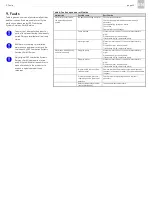
Page 44: ...sure that they are properly fitted If necessary you can clean the product using gentle material appropriate cleaning agents no alkalis no soap For safety reasons the product should be disconnected from the hydraulic and or compressed air supplies before cleaning During cleaning it is important to make sure that no cleaning agent enters the inside of the product If the system is operated normally w...

Page 45: ... cable and connect properly if necessary Check operating voltage on motor Check fuse Check motor circuit breaker Pump blocked Measure motor current If current is impermissibly high Dismantle pump crank by hand If resistance is high replace the pump Motor jammed Measure motor current If current is impermissibly high Dismantle motor crank by hand If resistance is high replace the motor Motor runs wi...

Page 46: ...esistance is high replace the motor Incorrect rotational direction of motor Check whether rotational direction corresponds to direction indicated by arrow change rotational direc tion if necessary Pressure regulating valve does not close Check pressure regulating valve to make sure that cracking pressure is correct and that there is no contamination or damage If cracking pressure is incorrect or i...

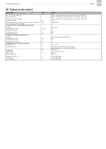
Page 47: ...c metal Pressure regulating valve bar 30 Pressure relief valve Included Protection class IP54 Pumped medium Mineral or synthetic oil NBR and FPM compatible Permitted oil viscosity 2 mm2 s cSt 20 to 1500 Motor Type Capacitor motor Rated voltage V 115 and 230 Rated current A 1 06 1 36 and 0 53 0 68 Rated frequency Hz 50 60 Rated output W 60 75 Rated speed RPM 2600 3050 Operating mode per VDE 0530 St...

Page 48: ...ed in compact unit Function NO contact Switching voltage max V AC DC 42 Switched current max A 2 5 Switching capacity max VA 100 Switching pressure bar 20 Level switch contained in compact unit Function NC contact opens when oil level falls Switching voltage max V AC 250 Switched current max A 0 7 Switching capacity max VA 50 Pressure switch for minimum air pressure Switching pressure bar 1 to 10 ...

Page 49: ...blank page ...

Page 50: ...blank page ...

Page 51: ...blank page ...

Page 52: ...ubricant selected by the user to make sure that it is suitable for conveyance in centralized lubrication systems All lubrication systems and components that are manufactured by SKF Lubrication Systems Germany GmbH are not approved for use in conjunction with gases liquefied gases gases dissolved under pressure vapours and fluids with a vapour pressure of more than 0 5 bar above normal atmospheric ...

Reviews: