background image

3  Installation – general recommendations

3.2.3 Handling – Transportation

Observe relevant transport regulations during transportation 

When the shipment is received, immediately check that no dam-

age has been done during transportation  If not, immediately inform 

the shipping company and SKF  If the shipment has been damaged, 

do not commission it 

Use suitable load suspension devices for transport and assembly  

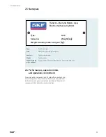
Weights of cylinder and any gear and motor are indicated on 

corresponding nameplates  If not, please read the technical docu-

mentation of the corresponding manufacturer 

In case of a problem, please contact your local SKF representative 

3.2.4 General recommendations for installation

When mounting the cylinder, check that all parts to which it is fixed 

are correctly aligned  This should be done throughout the complete 

stroke  

NOTE:

 Poor alignment will reduce the life of the cylinder 

Radial load or bending torque must not be applied to the cylinder 

pushing tube  Otherwise cylinder lifetime might be drastically 

reduced  

Avoid shocks on the pushing tube  Do not hit it with a hammer 

Check that cylinder can move freely and there is no obstruction 

over the full stroke 

Do not modify any part of cylinder

Do not add any part/component on cylinder

3.3 Electrical installation

3.3.1 Motor

Generally, please read the technical documentation from the motor 

manufacturer to know how to properly install the motor  The details 

concerning the motor can be found on its nameplate 

If the motor manufacturer doesn’t supply paper documentation or 

documentation CD-ROM, it means that a user manual can be down-

loaded from the manufacturer’s web site  

In case of a problem and if motor has been sold by SKF, please 

contact your local SKF representative  Otherwise, please contact 

motor supplier 

Note

During actuator handling, please 

take care not to damage the limit 

switches and home switch (if these 

options have been taken) 

!

Note

If actuator has no anti-rotation on 

the force tube, it is possible to extend or 

retract by turning force tube by hand 

!




DANGER

During and after operation, some parts of the 

cylinder carry dangerous voltages  Electric 

shock hazard  Risk of serious or fatal injuries 

Strictly observe the safety instructions in 

this manual and the safety instructions of 

manuals associated with each commissioned 

equipment (motor, servoamplifier, etc) 

Do not unplug motor connectors before 

switching off the power supply of the corre-

sponding servoamplifier  First unplug the 

signal connector and then the power 

connector 

Motor rotation can create voltage  Do not 

touch connector pins 

18

Summary of Contents for SLSA

Page 1: ...Installation operation and maintenance manual Electric cylinders SRSA SVSA and SLSA...

Page 2: ...2...

Page 3: ...ortant notes 15 3 2 Mechanical installation 16 3 2 1 Cylinder dimensions Cylinder drawing 16 3 2 2 Visual cylinder position Lt0 and Lt definition 16 3 2 3 Handling Transportation 18 3 2 4 General reco...

Page 4: ...ance upkeep and routine checks 35 5 1 SKF maintenance service 35 5 2 Lubrication detailed description 36 5 2 1 Roller screw or ball screw 37 5 2 2 Bearings 37 5 2 3 Profile rail guides 37 5 2 4 Spheri...

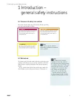
Page 5: ...ion If precautionary measures aren t taken it could result in death serious injury or property damage 1 2 Manual use This manual gives information and advice for the commissioning and maintenance of S...

Page 6: ...levant regulations 1 4 Exclusion of liability SKF does not assume liability for injury to persons or damage to equipment or property resulting from non observance of these operating instructions In su...

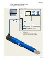
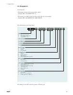
Page 7: ...of SKF cylinders includes Cylinder Motor power cable Motor sensor cable Motion controller Electronic interface to make connection between PC and motion controller To know the exact definition of SKF s...

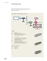
Page 8: ...tion controller Sensors limit switches home switch 1 Motor power cable 2 Motor sensor cable 3 Possible communications with external environment if necessary analog digital inputs outputs fieldbus 4 Co...

Page 9: ...t and pushing tube of cylinder red color 4 Pushing tube of cylinder Sc Translation speed of pushing tube x Translation move of pushing tube 5 Anti rotation of pushing tube Depending on cylin der defin...

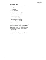
Page 10: ...er with motor in parallel without gear r rb with rb belt system ratio Cylinder with motor in parallel and gear r rb rg 2 3 Detailed description of supplied product Generally a detailed description of...

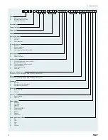
Page 11: ...ong lead ball screw Linear unit only Screw diameter Screw lead Stroke Rear attachment T Trunnions Z Special N No attachment Front attachment R Rod end F Rod end with fork Z Non standard N No attachmen...

Page 12: ...ches and 1 home switch S 2 limit switches only M 1 limit switch and 1 home switch L 1 limit switch only H 1 home switch only N No switch Interface and gear ratio If required see SKF catalogue PUB 1717...

Page 13: ...ith gear 2 6 Performances operation limits and operation environment For more details please read the SKF sales offer and other docu ments for approval The cylinder s performance and operational limit...

Page 14: ...n cylinder can be used by following general recommendations for use see paragraph 4 2 General recommendations for use After three years of storage we recommend that the cylinder is returned to SKF and...

Page 15: ...arting to install or to use the product WARNING Risk of serious or fatal injuries by crushing because of vertical load fall Do not use the brake of the motor or an additional brake to hold a vertical...

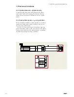
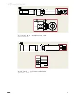
Page 16: ...upplied product 3 2 2 Visual cylinder position Lt0 and Lt definition During mechanical installation or cylinder operation it is sometimes required to know the cylinder position in relation to the zero...

Page 17: ...ecommendations Then it s required to measure Lt equivalent dimension of Lt0 when cylinder is in any position Then cylinder position in relation to the zero position given in the cylinder drawing is eq...

Page 18: ...y any part of cylinder 6 Do not add any part component on cylinder 3 3 Electrical installation 3 3 1 Motor Generally please read the technical documentation from the motor manufacturer to know how to...

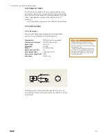
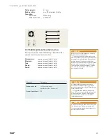
Page 19: ...nufacturer IFM Electronic or equivalent Manufacturer reference IFC207 or equivalent Sensor type Inductive Technology DC PNP Output Normally closed Supply voltage V DC 24 Consumption mA 10 with 24 V DC...

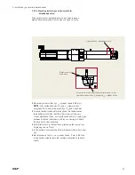
Page 20: ...il it touches the roller screw nut see cross section view above Then unscrew the limit switch to create a gap between it and the rollerscrew nut Stop unscrewing just before the limit switch stops dete...

Page 21: ...t touches the roller screw nut see cross section view above Then unscrew the limit switch to create a gap between it and the rollerscrew nut Stop unscrewing just before the limit switch stops detectin...

Page 22: ...mA 10 with 24 V DC Max current output mA 100 Connection M12x1 plug WARNING All technical data given here have been extracted from manufacturer s catalogue when this manual was edited They are given fo...

Page 23: ...ss section view above Then unscrew the limit switch to create a gap between it and the rollerscrew nut Stop unscrewing just before the limit switch stops detecting 3 Fix the limit switch in that posit...

Page 24: ...rnal wiring mode fig 2 Fig 1 Fig 2 3 3 6 Cables for sensors If cables for limit switches and or home switch and or temperature sensor have been taken the following information will be required to make...

Page 25: ...anufacturer s catalogue when this manual was edited They are given for information only If the brake manufacturer changes this data SKF is not responsible for any problem arising from such changes Ple...

Page 26: ...ching references in required documentations are 951 170 203 Assembly instructions KFG KFGS KFGC 1 3030 Sales brochure KFG KFGS KFGC In case of a problem please contact your local SKF representative 3...

Page 27: ...s technical documentation 4 3 Save modifications in non volatile memory WARNING During operation the cylinder surface temperature can reach high values There s a risk of burns or fire Before any work...

Page 28: ...If a home switch has been installed check its operation by moving the cylinder slowly and gradually to a position where the home switch status changes 10 Make a program for defining the zero referenc...

Page 29: ...information on that subject please read paragraph 5 2 Lubrication detailed description 4 3 How to define zero reference To define zero reference by using the home switch there are two ways to do it Th...

Page 30: ...chine driven by the SKF cylinder In this case depending on the servoamplifier definition read servo amplifier user manual to get corresponding information it might be necessary to make sure that the l...

Page 31: ...ehaviour is estimated through measurements made with the servoamplifier scope tool see servoamplifier technical documentation for more details while the cylinder is making forward and backward moves T...

Page 32: ...e tracking error fault and or over speed fault If the risk is low increase speed value and acceleration deceleration values and remake measurements with the scope tool during a forward backward cylind...

Page 33: ...over speed fault is established at 230 mm s for example and if this graph stays identical on several forward backward movements then the risk of generating an overspeed fault is very low 2 The value o...

Page 34: ...current loop speed loop and position loop As a general rule these parameters are adapted well enough so that the cylinder can correctly complete the tasks requested by the user But it is the user s re...

Page 35: ...inally sold by SKF This service includes complete disassembly cleaning and re assembly of the motor Visual inspection is done on all components All of the following components are replaced Bearings Se...

Page 36: ...recommendations have to be taken as a guide In most need cases these recommendations result in good lubrication conditions during the cylinders lifetime But it may occur depending on the ambient tempe...

Page 37: ...oved The state of the old grease can be seen and the quantity and period of re lubrication modified to suit the real operating conditions temperature speed load etc While re lubricating the old grease...

Page 38: ...5 Maintenance upkeep routine checks Fig 2 Fig 1 Fig 3 38...

Page 39: ...nsion every year measured through a trap door Correct air gap dimension See user manual specific data Opening time See user manual specific data Closing time See user manual specific data 5 3 2 Belt I...

Page 40: ...chanical malfunctions Malfunction Possible cause s Possible solution s Cylinder doesn t move Motor brake blocked Check brake connection and supply voltage System moved by cylinder blocked Check mobili...

Page 41: ...fault number possible causes are suggested with associated solutions Cylinder doesn t move in correct direction Incorrect motor resolver connection or incorrect servoamplifier parameter Check motor c...

Page 42: ...e reproduced even extracts unless prior written permission is granted Every care has been taken to ensure the accuracy of the information contained in this publication but no liability can be accepted...

Reviews: