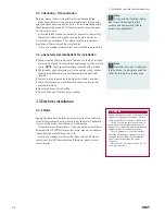
2.2 Operating principle
2 General notes
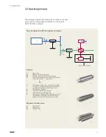
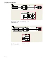
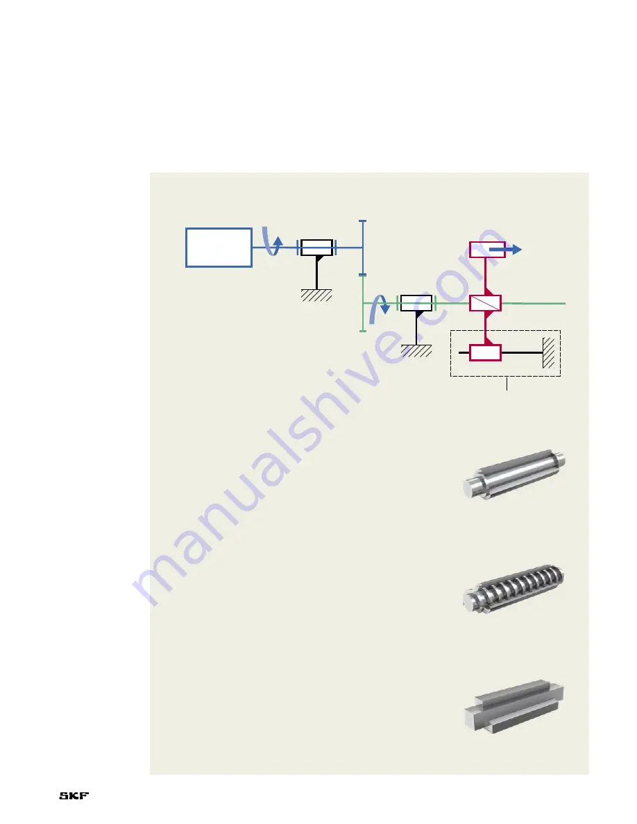
The operating principle of SKF electromechanical cylinders
Comments
1
Motor rotor
ω
a
Rotating speed of motor shaft
ω
b
Rotating speed of roller screw or ball screw
2
Gear system between motor shaft and roller screw
(or ball screw) shaft
r
is gear ratio
ω
a
r
=
–––
ω
b
3
Roller screw or ball screw = screw gear changing
rotation of screw (green color) into translation of
nut and pushing tube of cylinder (red color)
4
Pushing tube of cylinder
Sc
Translation speed of pushing tube
x
Translation move of pushing tube
5
Anti-rotation of pushing tube Depending on cylin-
der definition, this system is integrated into the
cylinder or located on the customer’s machine
Description of kinematic joints
J
1
Revolute joint
J
2
Screw joint
J
3
Prismatic joint
J
1
J
2
J
3
The operating principle of SKF electromechanical cylinders is described
by the cinematic drawing below (established in accordance with
NF EN ISO 3952-1 standard)
J
1
J
1
J
2
J
3
w
a
w
b
S
c
x
1
2
3
4
5
Anti-rotation system
9

