IX
05-03-5
A16D0IA
1
2
A
1
Turn puller handle and sliding half at once to extract
the bushing.
INSTALLATION
Countershaft
F-Series and S-Series Only
Should installation procedure be required, refer
to BRAKE 05-05 then look for
Brake Disc and
Countershaft Bearing Adjustment
.
IMPORTANT:
Large bushing retaining screws and
washers must be removed before small bushing
installation.
Coat bushing outside diameter with Loctite 609
(P/N 413 7031 00).
Install bushing as following photo.
All Models
Check end play of driven pulley on countershaft by
pushing pulley towards outer housing so that the inner
shims ( P/N 504 1082 00) contact it. Measure end play
at the mounting screw end between shim(s) and puley.
See illustration.
TYPICAL — TOP VIEW
1. Shim (P/N 504 1082 00) (as required)
2. Contact
A. 0 to 1 mm (0 to 3/64 in)
Torque retaining screw
no. 13
to 25 N•m (18 lbf•ft).
ADJUSTMENT
Refer to PULLEY DISTANCE AND ALIGNMENT 05-04
to adjust pulley distance. Adjust drive belt height
between pulley halves to obtain specified belt
deflection.
Reinstall the pulley on the countershaft by rever-
sing the removal procedure.
A03D1YA
529 0313 00
529 0312 00
A03D1ZA
529 0313 00
529 0312 00
Cam
Coat cam
no. 18
interior with anti-seize lubricant.
ASSEMBLY
Came Slider Shoe
Section 05 TRANSMISSION
Subsection 03 (DRIVEN PULLEY)
When replacing slider shoes
no. 4
, always install a new
set (3 shoes) to maintain equal pressure on the cam.
Assemble driven pulley components by reversing
the disassembly procedure.
Always apply anti-seize lubricant (P/N 413 7010
00) on the countershaft before final pulley
installation.
CAUTION
▼
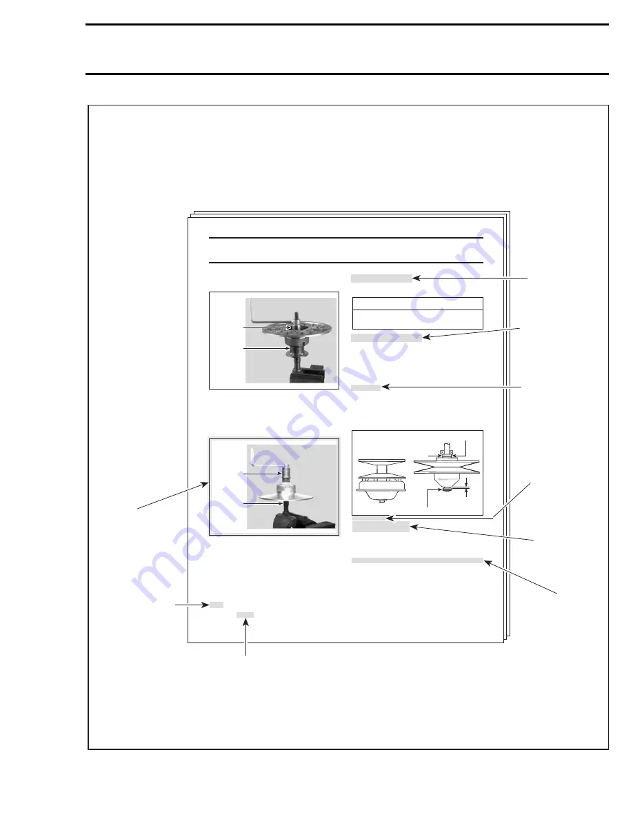
TYPICAL PAGE
Title indicates
main procedure
to be carried-out.
Reference to look
up a certain section
and subsection.
In this case it concerns
pulleys adjustment.
Italic bold face setting
in this case indicates
that particular
procedure for
F and S-Series is
finished, so from
this point, all models
are concerned.
Illustration always
follows text to which
it pertains.
A01A27S
Subtitle indicates
a particular procedure
for the named part.
Number following part name
refers to exploded view
at beginning of subsection.
Call-outs for
above illustration.
Italic bold face type
setting indicates a
particular procedure
concerning a model.
"TYPICAL" caption
indicates a general
view which does
not represent full
detail.
"TOP VIEW"
caption helps you
in understanding
illustration.
INTRODUCTION
Summary of Contents for Formula MACH 1
Page 1: ......
Page 277: ...FORMULA 111 600 600 R 600 LT 700 700 R MACH 1 1 R ANNEX 1...
Page 278: ......
Page 279: ......
Page 280: ......
Page 281: ......
Page 282: ......
Page 283: ...MACH Z Z R Z LT Z LT R ANNEX 2...
Page 284: ......
Page 285: ......
Page 286: ......
Page 287: ......
Page 288: ......
Page 289: ...GT 700 ANNEX 3...
Page 290: ......
Page 291: ......
Page 292: ......
Page 293: ......
Page 294: ......
Page 295: ......
Page 296: ...GT SE ANNEX 4...
Page 297: ......
Page 298: ......
Page 299: ......
Page 300: ......
Page 301: ......
Page 302: ......
Page 303: ......
Page 304: ......


