Section 05
TRANSMISSION
Subsection 04
(DRIVEN PULLEY)
05-04-2
REMOVAL
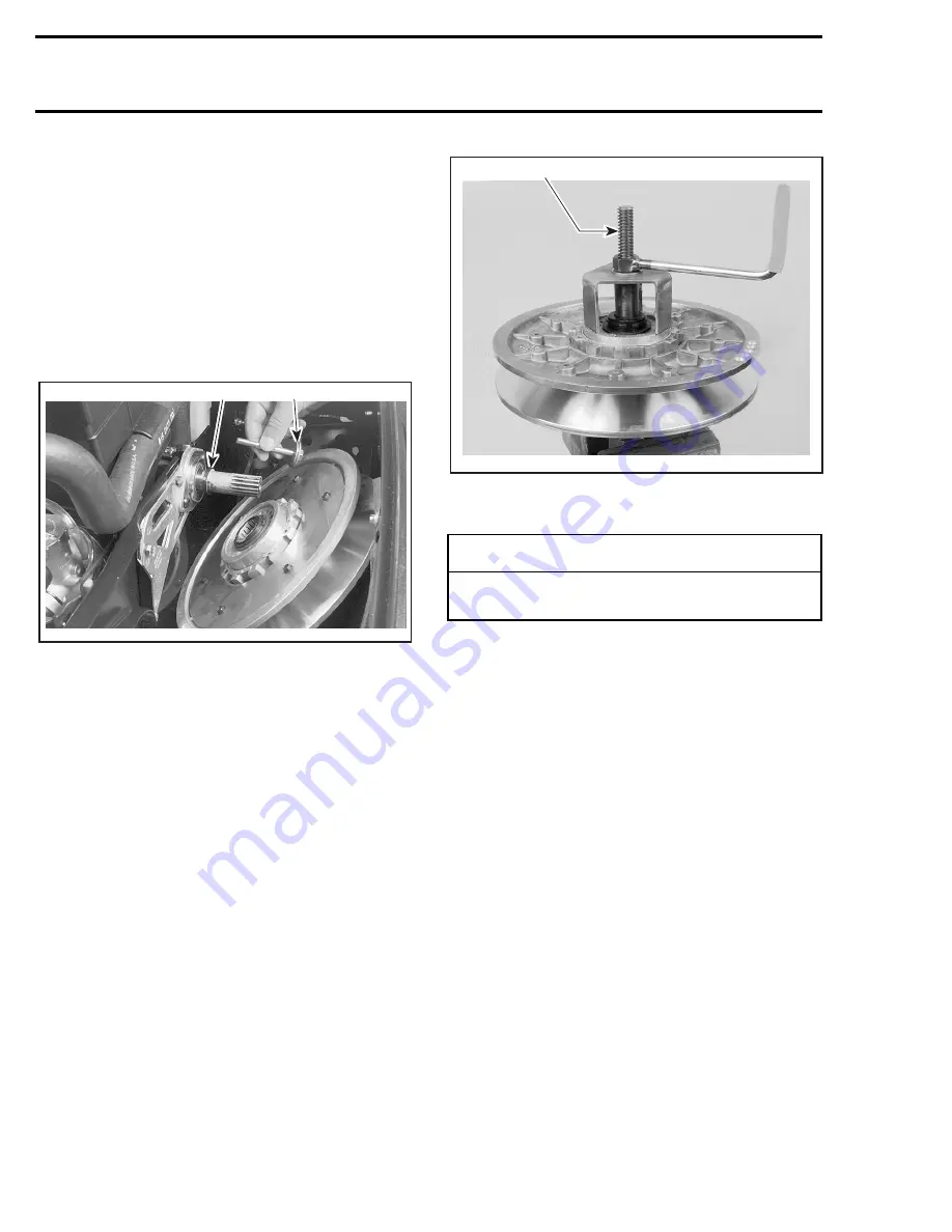
Remove belt guard and drive belt from vehicle.
Remove cap screw
no. 13
, lock washer
no. 12
and shouldered
washer
no. 11
then pull the driv-
en pulley from the countershaft.
Note shouldered washer position for reinstalla-
tion.
Take care not to loose spacer(s)
no. 2
. There may
be more than a spacer but the total spacer thick-
ness is always 7 mm (.276 in).
1. Spacer
2. Shoulder on this side
1, Countershaft
Should countershaft
no. 1
removal be required,
refer to BRAKE 05-06 then look for
Countershaft
and Brake Disc Removal
.
DISASSEMBLY
Use spring compressor (P/N 529 0186 00).
Remove snap ring
no. 3
and washer
no. 4
to dis-
assemble the outer cam and the 2 pulley halves.
CLEANING
9,10, Large Bushing and Small Bushing
During break-in period (about 10 hours of use), te-
flon from bushing moves to cam or shaft surface.
A teflon over teflon running condition occurs,
leading to low friction. So it is normal to see gray
teflon deposit on cam or shaft. Do not remove
that deposit, it is not dust.
When a dust deposit has to be removed from the
cam or the shaft, use dry cloth to avoid removing
transferred teflon.
Pulley Half Cleaning
Use Loctite Safety Solvent (P/N 413 7082 00).
A30D0HA
2
1
◆
WARNING
Driven pulley cam is spring loaded, use
above mentioned tool.
A30D0IA
529 0186 00
Summary of Contents for Formula MACH 1
Page 1: ......
Page 277: ...FORMULA 111 600 600 R 600 LT 700 700 R MACH 1 1 R ANNEX 1...
Page 278: ......
Page 279: ......
Page 280: ......
Page 281: ......
Page 282: ......
Page 283: ...MACH Z Z R Z LT Z LT R ANNEX 2...
Page 284: ......
Page 285: ......
Page 286: ......
Page 287: ......
Page 288: ......
Page 289: ...GT 700 ANNEX 3...
Page 290: ......
Page 291: ......
Page 292: ......
Page 293: ......
Page 294: ......
Page 295: ......
Page 296: ...GT SE ANNEX 4...
Page 297: ......
Page 298: ......
Page 299: ......
Page 300: ......
Page 301: ......
Page 302: ......
Page 303: ......
Page 304: ......


