Section 07
REAR SUSPENSION
Subsection 02
(SC-10 SUSPENSION)
07-02-7
20, Stopper Strap
Inspect strap for wear or cracks, bolt and nut for
tightness. If loose, inspect hole for deformation.
Replace as required. Make sure it is attached
through proper hole from the end. Refer to TECHNI-
CAL DATA 10-03. Torque nut to 11 N•m (97 lbf•
in
).
1. 1
st
hole
2. 2
nd
hole
A. 11 N•m (97 lbf•
in
)
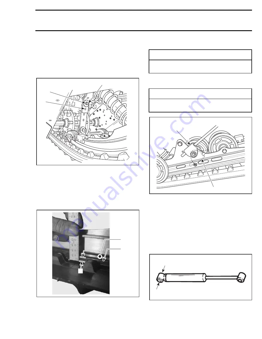
17, Slider Shoe
Measure slider shoes from the bottom to the
0.5 mm (.020 in) radius as shown on the next photo.
Minimum thickness must be 2 mm
(.080 in).
TYPICAL
1. Slider shoe
2. Molding line (this line is not the wear limit)
A. Wear limit measurement (must be at least 2 mm (.080 in))
Replace slider shoes when wear limit is reached.
18, Spring Support
RIGHT SIDE SHOWN
1. Right position: upward
2. Wrong position
SHOCK ABSORBER INSPECTION
All Models Equipped with Hydraulic Shock
NOTE:
Hydraulic shocks are painted black or dark
gray.
Secure the shock body end in a vise with its rod
upward.
1. Clamp
A03F0QA
A
1
2
A01F2MA
1
2
A
-
CAUTION
Slider shoes must always be replaced in
pairs.
-
CAUTION
To avoid track damage, spring supports
must be mounted upward.
A03F0VA
1
2
A14F0BA
1
Summary of Contents for Formula MACH 1
Page 1: ......
Page 277: ...FORMULA 111 600 600 R 600 LT 700 700 R MACH 1 1 R ANNEX 1...
Page 278: ......
Page 279: ......
Page 280: ......
Page 281: ......
Page 282: ......
Page 283: ...MACH Z Z R Z LT Z LT R ANNEX 2...
Page 284: ......
Page 285: ......
Page 286: ......
Page 287: ......
Page 288: ......
Page 289: ...GT 700 ANNEX 3...
Page 290: ......
Page 291: ......
Page 292: ......
Page 293: ......
Page 294: ......
Page 295: ......
Page 296: ...GT SE ANNEX 4...
Page 297: ......
Page 298: ......
Page 299: ......
Page 300: ......
Page 301: ......
Page 302: ......
Page 303: ......
Page 304: ......


