Section 08
STEERING/FRONT SUSPENSION
Subsection 02
(STEERING SYSTEM)
08-02-5
BUSHING INSTALLATION
17,18, Ball Joint
(left hand and right hand threads)
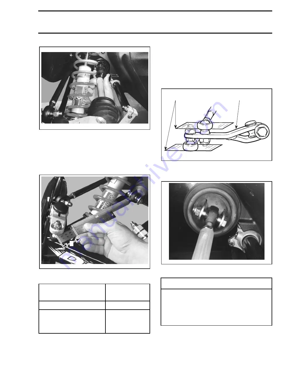
The maximum external threaded length not en-
gaged in the tie rod must not exceed the value
L
in the following thread length chart:
TYPICAL
L: Threaded length not engaged
The ball joint should be restrained when tighten-
ing the tie rod end lock nut. Align it so the tie rod
end is parallel to the steering arm when assem-
bled on the vehicle, refer to the following illustra-
tion.
For proper torque specifications refer to the spe-
cific exploded view for the vehicle being serviced.
TYPICAL
1. Parallel with steering arm
2. Steering arm
TIE ROD BALL JOINT PARALLEL TO BRACKET BEFORE
TIGHTENING
MODEL
L
mm
(in)
Outer ball joint of tie rods
46
(1-13/16)
Both ball joints of short tie rod
(linking steering column to
pivot arm) and inner ball joint of
tie rods
34
(1-11/32)
A30G09A
A30G0AA
L
◆
WARNING
The cut off section of the ball joint must run
parallel with the steering arm. When tighten-
ing lock nuts, restrain ball joint with appro-
priate size wrench. Ensure not too many
threads are kept outside of the tie rod ac-
cording to the thread length chart.
A02G0IA
1
2
A30G0MA
Summary of Contents for Formula MACH 1
Page 1: ......
Page 277: ...FORMULA 111 600 600 R 600 LT 700 700 R MACH 1 1 R ANNEX 1...
Page 278: ......
Page 279: ......
Page 280: ......
Page 281: ......
Page 282: ......
Page 283: ...MACH Z Z R Z LT Z LT R ANNEX 2...
Page 284: ......
Page 285: ......
Page 286: ......
Page 287: ......
Page 288: ......
Page 289: ...GT 700 ANNEX 3...
Page 290: ......
Page 291: ......
Page 292: ......
Page 293: ......
Page 294: ......
Page 295: ......
Page 296: ...GT SE ANNEX 4...
Page 297: ......
Page 298: ......
Page 299: ......
Page 300: ......
Page 301: ......
Page 302: ......
Page 303: ......
Page 304: ......


