Section 04
ENGINE
Subsection 02
(599, 699 AND 809 ENGINE TYPES)
04-02-7
17,18, Cylinder and Piston
NOTE:
Be sure to restore the chamfer around all
cylinder sleeve port openings.
Before inserting piston in cylinder, lubricate the
cylinder with new injection oil or equivalent.
1,2,17, Cylinder Head Cover, Cylinder
Head and Cylinder
Check flatness of part sealing surfaces.
Refer to LEAK TEST AND ENGINE DIMENSION
MEASUREMENT 04-03 and look for
Checking
Surface Flatness
.
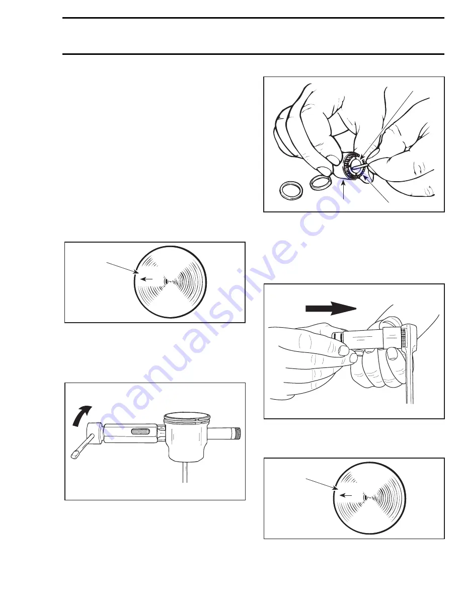
– Mount piston over connecting rod with the let-
ters “AUS” (over an arrow on the piston dome)
facing in the direction of exhaust port (see illus-
tration below).
1. Exhaust
599 and 699 Engines
– Install piston pin puller (P/N 529 0210 00) and
turn handle until piston pin is correctly posi-
tioned in piston.
– Remove piston pin puller.
809 Engine
When reinstalling original needle bearings, make
sure that 31 needles are inserted between expan-
sion sleeve and locating sleeve.
1. Expansion sleeve
2. 31 needles
3. Locating sleeves
– Grease thrust washers and install them on each
end of needles.
– Using a 21 mm (.826 in) diameter pusher, insert
needles into connecting rod.
Mount piston over connecting rod with the letters
“AUS” (over an arrow on the piston dome) facing
in the direction of exhaust port.
1. Exhaust
A01C01A
AUS
1
A21C01A
A21C03A
1
2
3
A21C02A
A01C01A
AUS
1
Summary of Contents for Formula MACH 1
Page 1: ......
Page 277: ...FORMULA 111 600 600 R 600 LT 700 700 R MACH 1 1 R ANNEX 1...
Page 278: ......
Page 279: ......
Page 280: ......
Page 281: ......
Page 282: ......
Page 283: ...MACH Z Z R Z LT Z LT R ANNEX 2...
Page 284: ......
Page 285: ......
Page 286: ......
Page 287: ......
Page 288: ......
Page 289: ...GT 700 ANNEX 3...
Page 290: ......
Page 291: ......
Page 292: ......
Page 293: ......
Page 294: ......
Page 295: ......
Page 296: ...GT SE ANNEX 4...
Page 297: ......
Page 298: ......
Page 299: ......
Page 300: ......
Page 301: ......
Page 302: ......
Page 303: ......
Page 304: ......


