background image


Copyright by SKIDATA AG 2004 

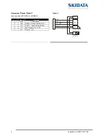
Pin Description - Desktop Versions

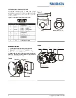
All desktop Versions have a cable with D-type 
subminiature connector with 9 pins; receptable (=female) 
housing.  A plug-in power supply, connected to the cable, 
is also be included. 
 

Figure 1 - connector-receptable, front view

1

2

3

4

5

6

7

8

9


Pin # 

Signal 

Function 

1 - 


not 

connected 

RxD / A 


RS232: 

Receive Data 

 RS485: Signal 

TxD / B 


RS232: 

Transmit Data 

 RS485: Signal 

4 - 


not 

connected 

5 GND 


Power 

Ground 


RS232: Signal Ground 

6 - 


not 

connected 

7 - 


not 

connected 

8 - 


not 

connected 

Vin 


Power Supply Voltage 

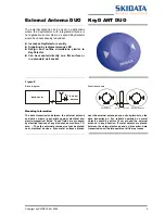
Figure 2 

140

130

25

12

0

60

Mounting Plate

 (bottom view)

Casing


Installing  KD DUO 

1.  Thread cable through bottom section and fasten 
2.  Screw bottom section to mounting socket 

NOTE: Ensure correct alignment of TOP marking 

3.  Screw top cover to bottom section 
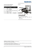
All cables must be fed in vertically to prevent water from 
leaking in.  Adjust cable feed as needed.  Note that fixing 
screws are not included in delivery  
 

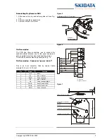
Figure 3 

Cable hole

Fixing screw

Break-out for mounting

Snap-in latch


Figure 4 
 

Cover

PCB

Bottom
section

Cable

Concealed 
mounting socket

Cable feed hole 
(desktop version)


Summary of Contents for KeyD 232 DUO

Page 1: ...Manual and operational description Reading Device KeyD 232 DUO KeyD 485 DUO KeyD ANT DUO...

Page 2: ...ilation of this Technical Documentation great care has been taken to ensure the accuracy of the information contained in it However despite our constant effort to ensure the highest degree of accuracy...

Page 3: ...device must accept any interference received including interference that may cause un desired operation FCC 15 21 IMPORTANT Any changes to or modifications of KeyDetector DUO unless expressly approve...

Page 4: ...Detector DUO Page 4 SKIDATA AG February 2004 KeyDetector DUO 1 Document Management Version Table Tab 1 Document Version Table for Installation Maintenance Instructions Section Document Pages Version D...

Page 5: ...ed near electrical devices Also metal surfaces placed near the KeyDetector have a strong impact on the data transmissions For sure and reliable operation it is neccessary that there are no metal objec...

Page 6: ...Signal Ground 6 not connected 7 not connected 8 not connected 9 Vin Power Supply Voltage Figure 2 140 130 25 120 60 Mounting Plate bottom view Casing Installing KD DUO 1 Thread cable through bottom se...

Page 7: ...rsion To attach an external antenna optional see Fig 10 Pin Description Connector power data 1 This is an 8 pin connector fixed by screws Cable diameter 0 14 mm 0 75 mm Pin Signal Function 1 IN 3 Inpu...

Page 8: ...JST PHR 5 or JST 08KR Pin Signal Function 1 GND Power Ground 2 RxD RS232 Receive Data KD DUO 3 TxD RS232 Transmit Data KD DUO 4 Vin Power supply 9 to 12 VDC 5 IO1 Signal in out Figure 8 1 2 3 4 5 GND...

Page 9: ...e KeyDetector inside Wall outside External Antenna 2 2 Mounting Information The data transmission between the external antenna and data carriers is sensitive against electrical and electro magnetical...

Page 10: ...antenna To connect and fasten the coaxial cable Insert metal tongue between cable shield and insulation Fasten cable tie SKIDATA AG Untersbergstra e 40 A 5083 Gartenau p 43 6246 888 0 f 43 6246 888 7...

Reviews: