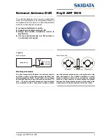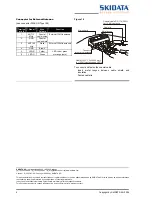
Copyright by SKIDATA AG 2004
3
Deinstalling KeyDetector DUO
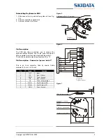
1. Slide opener into top and bottom guide rail (see Fig.
12).
2. Pull lever upwards or downwards
3. Pull lever out and lift off cover
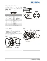
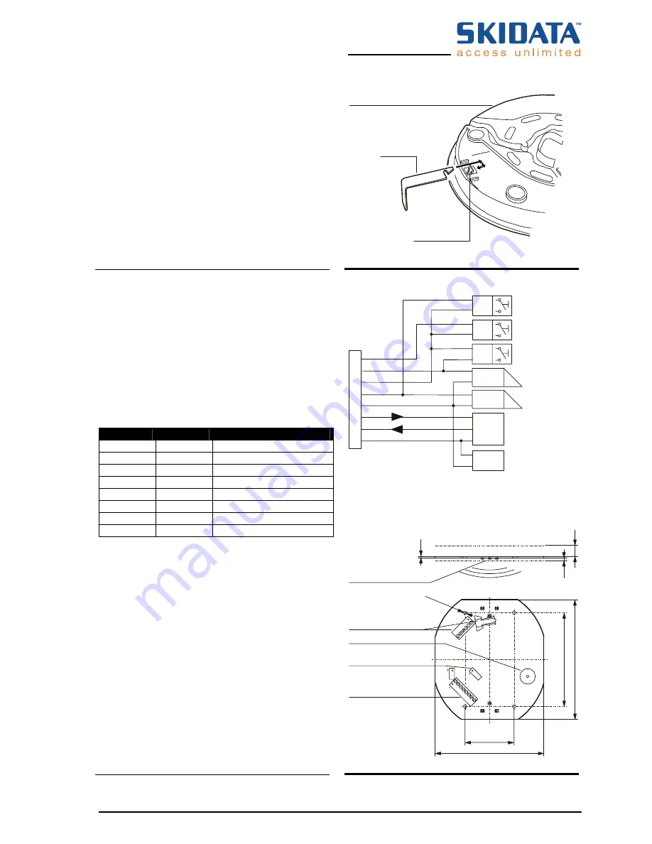
Figure 5
KeyDetector DUO – Rear view
Opener
Opener –
Snap-in latch
Figure 6
Pin Description
The PCB has three connectors, one to connect the
optional external antenna, one for the power supply and
data, separate for surface mount and desktop version.
To attach an external antenna (optional), see Fig. 10.
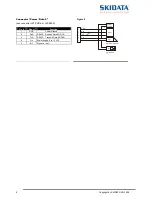
Pin Description – Connector “power / data 1”
This is an 8 pin connector, fixed by screws. Cable
diameter: 0,14 mm² - 0,75 mm².
Pin
Signal
Function
1
IN 3
Input
2
IO1
Input / Output
3 GND
Power
Ground
4
IO2
Input / Output
5
Vin
Power supply voltage
6
TxD/A
KeyD: Data out KD
7
TxD/B
KeyD: Data in KD
8 GND
Power
Ground
1
2
3
4
5
6
7
8
IN3
GND
IO1
RxD
GND
TxD
IO2
Vin
Power
supply
in
in
-
+
Host
2
2
1
1
1
1
2
e.g. button
e.g. door opener
out
out
in
Figure 7
1.
6
ø3.2 (4
x)
86
11
0
10
2.
5
100
45
LEDs red/green/orange
Connector for external
antenna
beeper
Connector “power/data 2”
Connector “power/data 1”


