background image

60

Service

Preventive  maintenance  performed  by
unauthorized  personnel  may  result  in

misplacing  of  internal  wires  and  components  which  could
cause serious hazard. We recommend that all tool service be
performed by a Skil Factory Service Center or Authorized Skil
Service Station.

Carbon Brushes

The  brushes  and  commutator  in  your  tool  have  been
engineered  for  many  hours  of  dependable  service.  To
maintain  peak  efficiency  of  the  motor,  we  recommend  every
two to six months the brushes be examined. Only genuine Skil
replacement  brushes  specially  designed  for  your  tool  should
be used.

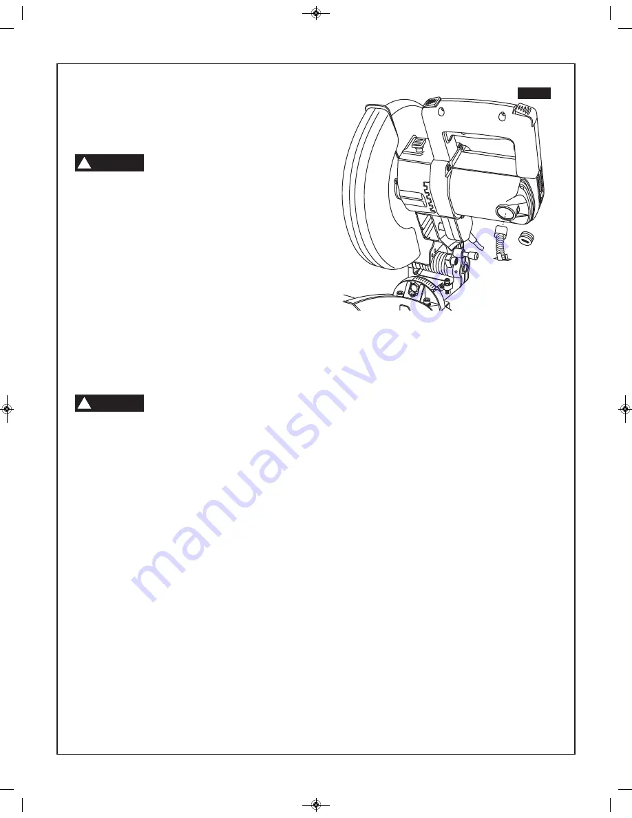
Motor Brush Replacement

To Inspect or Replace Brushes:

1.

Unplug the saw.

The  brush  cap  is  spring  loaded  by  the
brush assembly.

2.

Remove  the  brush  cap  on  the  motor  using  a  wide  flat
blade screwdriver.

3.

Pull  out  the  brush  (Figure  36).    Repeat  for  the  opposite
side.

NOTE:

If installing the existing brush or brushes, make sure

the  brush  goes  in  the  same  way  it  came  out.  Otherwise  a
break-in  period  will  occur  that  will  reduce  motor  performance
and increase brush wear.

4.

Install new brush.  The two (2) tabs on the brush terminal
go in the same hole the carbon part fits into.

5.

Tighten the brush cap but do not overtighten.

Maintenance and

Lubrication

15

0

45

33.9

30

FIG. 36

WARNING

!

CAUTION

!

SM 2610017175 08-11:SM 2610017175 08-11.qxp  8/2/11  11:24 AM  Page 60

Summary of Contents for 3316

Page 1: ...ons Consignes d utilisation de sécurité Instrucciones de funcionamiento y seguridad 1 877 SKIL999 1 877 754 5999 www skil com Call Toll Free for Consumer Information Service Locations Pour obtenir des informations et les adresses de nos centres de service après vente appelez ce numéro gratuit Llame gratis para obtener información para el consumidor y ubicaciones de servicio 3316 SM 2610017175 08 1...

Page 2: ...itions Water entering a power tool will increase the risk of electric shock Do not abuse the cord Never use the cord to carry the tools or pull the plug from an outlet Keep cord away from heat oil sharp edges or moving parts Replace damaged cords immediately Damaged cords increase the risk of electric shock When operating a power tool outside use an outdoor extension cord marked W A or W These cor...

Page 3: ...tions may create a hazard Safety Rules for Miter Saws Use clamps to support workpiece whenever possible If supporting the workpiece by hand you must always keep hand outside of No Hands area as marked with a symbol on the base Always use clamp to support workpiece when making compound cuts Do not use this saw to cut pieces that are too small to be securely clamped Your hand if placed inside the No...

Page 4: ... the workpiece This will help avoid thrown workpieces Before sawing always check that there is no interference between moving and stationary parts of the saw Do not operate the saw in the following range of miter and bevel combinations Left miter angles greater than 45 and bevel angles greater than 35 These miter and bevel combinations may result in interference between the lower guard and the wor...

Page 5: ... BELOW CAN BE FOUND ON YOUR TOOL THESE WARNINGS ARE ONLY A CONDENSED FORM OF THE MORE DETAILED SAFETY RULES AND PRECAUTIONS THAT APPEAR IN YOUR OWNER S MANUAL THEY SERVE AS A REMINDER OF ALL SAFETY RULES NEEDED FOR SAFE OPERATION OF THIS MITER SAW Safety READ ALL INSTRUCTIONS Failure to follow the SAFETY RULES identified by BULLET symbol listed BELOW and other safety precautions may result in seri...

Page 6: ...UCTIONS WARNING Connection to a Power Source WARNING WARNING WARNING Replace damaged cords immediately Use of damaged cords can shock burn or electrocute If an extension cord is necessary a cord with adequate size conductors should be used to prevent excessive voltage drop loss of power or overheating The table shows the correct size to use depending on cord length and nameplate amperage rating of...

Page 7: ...ons overload low voltage such as small size wire in the supply circuit or to overly long supply circuit wire Always check the connections the load and the supply circuit whenever motor does not work well Electric Brake Your saw is equipped with an automatic electric brake which is designed to stop the blade from spinning in about seven 7 seconds after you release the trigger switch It is useful wh...

Page 8: ...l Stop Screws Used to adjust the blade square against the base at 90 and at 45 degree bevel 11 Dust Collection Bag Attaches to the dust port and collects dust to help keep work area clean 12 Trigger Switch The power switch used with the ambidextrous switch energizes the unit 13 Lock Off Switch The left or right hand ambidextrous switch must be pressed to activate the power switch 14 Quick Clamp Kn...

Page 9: ...ves ou des pièces mobiles Remplacez les cordons abîmés immédiatement Les cordons abîmés augmentent le risque de secousses électriques Lorsque vous utilisez un outil électrique à l extérieur utilisez un cordon de rallonge pour service extérieur marqué W A ou W Ces cordons sont prévus pour usage extérieur et réduisent le risque de secousses électriques Sécurité personnelle Demeurez vigilant surveill...

Page 10: ...rage chaque fois que possible Si vous supportez l ouvrage à la main vous devez toujours garder la main à l extérieur de la zone interdite aux mains identifiée par un symbole sur la base Pour réduire le risque de blessure utilisez toujours la bride de fixation pour assujettir l ouvrage lorsque vous effectuez une coupe d onglet composée N utilisez pas cette scie pour couper des pièces qui sont trop ...

Page 11: ...ns d onglets et de biseaux angles d onglet à gauche de plus de 45 et angles de biseau de plus de 35 Ces combinaisons d onglets et de biseaux pourraient causer des interférences entre le dispositif de protection inférieur et la bride de fixation de l ouvrage N utilisez pas de lame de scie fonctionnant nominalement à moins de 5 000 tr mn N utilisez pas de lame plus grande ou plus petite que 10 po de...

Page 12: ...ENTS NE SONT QU UNE FORME CONDENSÉE DES RÈGLES ET PRÉCAUTIONS DE SÉCURITÉ PLUS DÉTAILLÉES QUI APPARAISSENT DANS VOTRE MANUEL ELLES SERVENT À VOUS RAPPELER TOUTES LES RÈGLES DE SÉCURITÉ NÉCESSAIRES À UNE UTILISATION SÛRE DE CETTE SCIE À ONGLET A S CONSERVEZ CES INSTRUCTIONS ZONE DÉSIGNÉE DE DANGER ÉVITER DE PLACER LES MAINS LES DOIGTS OU LES BRAS DANS LA ZONE DÉSIGNÉE PAR CE SYMBOLE Sécurité LISEZ ...

Page 13: ...SEMENT AVERTISSEMENT AVERTISSEMENT Remplacez immédiatement toute rallonge endommagée L utilisation de rallonges endommagées risque de provoquer un choc électrique des brûlures ou l électrocution En cas de besoin d une rallonge utilisez un cordon de calibre satisfaisant pour éviter toute chute de tension perte de courant ou surchauffe Le tableau ci contre indique le calibre des rallonges recommandé...

Page 14: ...nt tout contact entre la scie et le matériau Si l outil fonctionne mais le frein n arrête pas uniformément la lame en environ sept 7 secondes N utilisez PAS la scie et faites la réparer immédiatement L action de freinage de cette scie n est pas destinée à servir de mesure de sécurité N oubliez pas de laisser la lame de scie s arrêter complètement avant de la retirer du matériau Comme toujours le s...

Page 15: ... de travail plate 9 Clé hexagonale Sert à serrer ou à desserrer la lame 10 Vis de butée de biseau Sert à ajuster l équerre contre la base à des angles de biseau de 90 et 45 degrés 11 Sac de collecte de la poussière S attache à l orifice de dépoussiérage et collecte la poussière pour aider à assurer la propreté de la zone de travail 12 Interrupteur à gâchette L interrupteur utilisé avec le commutat...

Page 16: ...tenga el cordón alejado del calor el aceite los bordes afilados o las piezas móviles Cambie los cordones dañados inmediatamente Los cordones dañados aumentan el riesgo de que se produzcan sacudidas eléctricas Cuando utilice una herramienta mecánica a la intemperie use un cordón de extensión para intemperie marcado W A o W Estos cordones tienen capacidad nominal para uso a la intemperie y reducen e...

Page 17: ... la sección Mantenimiento de este manual El uso de piezas no autorizadas o el incumplimiento de las instrucciones de Mantenimiento puede constituir un peligro Normas de seguridad para sierras para cortar ingletes Use abrazaderas para soportar la pieza de trabajo siempre que sea posible Si soporta la pieza de trabajo con la mano siempre debe mantener la mano fuera del área de No tocar con la mano s...

Page 18: ...ferencia entre las partes móviles y estacionarias de la sierra No utilice la sierra en el siguiente intervalo de combinaciones de inglete y bisel Ángulos de inglete a la izquierda mayores de 45 y ángulos de bisel mayores de 35 Estas combinaciones de inglete y bisel pueden causar interferencia entre el protector inferior y la abrazadera para la pieza de trabajo No utilice una hoja de sierra con cap...

Page 19: ... LA HERRAMIENTA ESTAS ADVERTENCIAS SON SOLAMENTE UNA FORMA CONDENSADA DE LAS NORMAS Y PRECAUCIONES DE SEGURIDAD MAS DETALLADAS QUE APARECEN EN EL MANUAL DEL USUARIO SIRVEN COMO RECORDATORIO DE TODAS LAS NORMAS DE SEGURIDAD NECESARIAS PARA LA UTILIZACION CON SEGURIDAD DE ESTA SIERRA PARA CORTAR INGLETES Seguridad LEA TODAS LAS INSTRUCCIONES El incumplimiento de las NORMAS DE SEGURIDAD identificadas...

Page 20: ...STAS INSTRUCCIONES Conexión a una fuente de alimentación Cordones de extensión Sustituya los cordones dañados inmediatamente La utilización de cordones dañados puede causar shock quemar o electrocutar Si se necesita un cordón de extensión se debe utilizar un cordón con conductores de tamaño adecuado para prevenir caídas de tensión excesivas pér didas de potencia o sobrecalentamiento La tabla muest...

Page 21: ...e trabajo Si la herramienta funciona pero el freno no detiene la hoja cada vez en unos 7 segundos NO utilice la sierra y haga que se realice servicio de ajustes y reparaciones inmediatamente La acción de frenado de esta sierra no está proyectada como dispositivo de seguridad Recuerde dejar que la hoja de la sierra se detenga por completo antes de retirarla de la pieza de trabajo Como siempre el si...

Page 22: ...rnillos del tope de bisel Se utilizan para ajustar la hoja escuadrada contra la base a 90 grados y a un bisel de 45 grados 11 Bolsa de recolección de polvo Se conecta al orificio para polvo y recoge el polvo para ayudar a mantener limpia el área de trabajo 12 Interruptor gatillo El interruptor de alimentación utilizado con el interruptor ambidiestro enciende a la unidad 13 Interruptor de fijación ...

Page 23: ... sure all items are accounted for before discarding any packing material If any parts are missing do not plug in power cord or turn the switch on until the missing parts are obtained and are installed correctly Assembly Tools Needed For Assembly And Alignment Unpacking and Checking Contents Should be no Gap or Overlap when Square is Flipped Over in Dotted Position Draw Light Line on Board Along th...

Page 24: ...ranchez pas le cordon d alimentation électrique ou ne mettez pas l interrupteur en marche avant d avoir obtenu et installé correctement les pièces manquantes Assemblage Outils nécessaires à l assemblage et à l alignement Déballage et inspection du contenu Should be no Gap or Overlap when Square is Flipped Over in Dotted Position Draw Light Line on Board Along this Edge Straight Edge of Board 3 4 T...

Page 25: ...el cable de alimentación ni ponga el interruptor en la posición de encendido hasta que las piezas que falten se hayan obtenido y se hayan instalado correctamente Ensamblaje Herramientas necesarias para el ensamblaje y la alineación Desempaquetado y comprobación del contenido Should be no Gap or Overlap when Square is Flipped Over in Dotted Position Draw Light Line on Board Along this Edge Straight...

Page 26: ...lockwise to tighten Do Not Over Tighten 3 Loosen handle 1 4 turn or more and press down on the miter handle release 3 to unlock the miter table from the set position To lock tighten the handle Store the Saw Blade Wrench Store the blade wrench 4 in the clip at the rear of the saw base to prevent loss Figure 4 FIG 2 4 FIG 3 SM 2610017175 08 11 SM 2610017175 08 11 qxp 8 2 11 11 24 AM Page 26 ...

Page 27: ... la base de la scie pour ne pas risquer de la perdre Figure 3 Ensamblaje Instalación del pomo de fijación de inglete 1 Enrosque cuidadosamente el pomo de fijación de inglete 1 en el agujero 2 ubicado en la parte delantera de la mesa de inglete Figura 2 2 Gire el pomo de fijación de inglete en el sentido de las agujas del reloj para apretarlo No lo apriete excesivamente 3 Afloje el mango 1 4 de vue...

Page 28: ... may be explosive Do not throw sawdust on an open fire Spontaneous combustion may in time result from mixture of oil or water with dust particles When sawing chemically pressure treated lumber paint that may be lead based or any other materials that may contain carcinogens use special precautions A suitable respirator must be worn by all personnel entering the work area Work area should be sealed ...

Page 29: ...l étau 1 dans le trou de montage 2 prévu de l un quelconque des côtés de l avant de la base Figure 6 Instalación de la bolsa para polvo 1 Con el brazo de inglete fijo en la posición hacia abajo comprima las dos lengüetas ubicadas en la pinza de resorte deslice la bolsa sobre la acanaladura ubicada en el orificio para polvo Figura 5 y luego suelte las lengüetas 2 Posicione la bolsa para polvo de ma...

Page 30: ...rbor 8 Install the blade collar 6 in the proper orientation then install blade bolt 5 Figure 9 Tighten blade bolt 5 finger tight Press the arbor lock and tighten blade bolt 5 securely but do not overtighten 9 Align the guard plate with the guard plate screw hole and tighten the guard plate front screw 1 Figure 8 10 Rotate the lower guard down to tighten the guard plate rear screw 2 Figure 8 Never ...

Page 31: ... réparation afin d éviter tout risque de blessure REMARQUE nettoyez la lame en cas d accumulation d huile avant l installation 1 Appuyez légèrement sur la poignée et tirez sur la cheville de blocage de la tête 8 de façon à la faire sortir complètement puis soulevez la tête pour la mettre en position élevée Figure 7 2 Desserrez mais sans la retirer complètement la vis arrière de fixation de la plaq...

Page 32: ...tall screws lock washers and hex nuts Supporting surface where saw is to be mounted should be examined carefully after mounting to insure that no movement can occur during use If any tipping or walking is noted secure the workbench or stand before operating the compound miter saw Portable Mounting Using Clamps If necessary clamp the compound miter saw to a workbench or table top Place three or mor...

Page 33: ...ajo Monte la sierra en el banco de trabajo utilizando los cuatro 4 agujeros para pernos de 5 16 1 Compruebe que hay espacio libre a la izquierda y a la derecha de la sierra Figura 10 1 Cada uno de los cuatro 4 agujeros de montaje debe atornillarse firmemente usando tornillos de cabeza plana de 5 16 arandelas de seguridad y tuercas hexagonales no se incluyen 2 Localice y marque donde se va a montar...

Page 34: ...ailure to do so could cause you to lose control of the saw mounting assembly 4 Lower the saw to allow the front edge of the saw base to seat fully over the front rail figure 13 5 Check position and adjust if necessary to make sure the weight of the saw is evenly balanced over the rails as shown in figure 13 6 Rotate the two quick lock knobs 1 clockwise and securely tighten 7 Ensure the saw base is...

Page 35: ...e de la base de la scie afin de la désengager du rail avant du support Montaje de la sierra para cortar ingletes en la base de soporte No incluida disponible como accesorio Vea las Figuras 12 13 1 Gire los dos pomos de fijación rápida 1 ubicados a cada lado de la parte trasera de la base de la sierra en sentido contrario al de las agujas del reloj hasta que las abrazaderas se hayan retraído tanto ...

Page 36: ... 1 against the fence 2 and next to the blade 3 Figure 14 Avoid touching the saw teeth with the square The set in the blade s teeth will hold the square away from the blade The blade should contact the full length of the square 3 If the blade does not contact the full length of the square loosen the four fence adjustment screws 4 using a 9 16 14 mm socket or wrench not provided Figure 15 4 Hold the...

Page 37: ...4 NOTA La escuadra de combinación y la llave de tuerca no se suministran Ajustes ADVERTENCIA Débranchez la fiche de la prise de courant avant de procéder à de quelconques opéra tions d assemblage de réglage ou de réparation afin d éviter tout risque de blessure REMARQUE votre scie à onglets composés a été réglée complètement à l usine Il est toutefois possible que l alignement ait été affecté quel...

Page 38: ...he full length of the square is against the blade Tighten the bevel adjustment screw locknut 4 3 Make sure the bevel indicator is aligned with the bevel index 0 mark If adjustment is necessary loosen the bevel indicator screw 6 until the indicator aligns with the 0 mark Figure 18 4 Tighten the bevel indicator screw 6 Bevel Stop Adjustment Make sure the bevel stop screw is adjusted to 45 If adjustm...

Page 39: ...de fijación del tope de bisel 1 Ajustes Réglage de la base par rapport à la lame Assurez vous que la lame est perpendiculaire à la base 1 Tout en abaissant la lame maintenez une équerre à combinaison 1 contre la base 2 et adjacente à la lame 3 Figure 16 Évitez de mettre les dents de la scie en contact avec l équerre L inclinaison des dents de la scie maintiendra l équerre à distance de la lame La ...

Page 40: ...nder certain cutting conditions If this occurs Typically this may occur when trying to cut workpieces that are near the maximum cutting height capacity Under these conditions the workpiece can stop the lower guard movement before the downward motion of the arm could preopen the lower guard If this occurs Workpiece must be securely clamped This frees your left hand to raise the guard 1 by the lip 2...

Page 41: ...de manière à ne pas entraver le mouvement de coupe ou de nuire à la régularité du mouvement du capot protecteur inférieur AVERTISSEMENT Posición del cuerpo y de las manos Posicione el cuerpo y las manos de modo adecuado para hacer que las operaciones de corte sean más fáciles y seguras Siga las instrucciones siguientes Figura 21 Nunca ponga las manos cerca del área de corte Mantenga las manos fuer...

Page 42: ...ate screw knob 2 of the clamp clockwise to tighten counter clockwise to loosen 3 Move the head assembly to check clearance with clamp There may be extreme compound cuts where supplied clamp cannot be used Use conventional clamps Do not try to cut short pieces that cannot be clamped and cause your hand to be in the No Hands Zone Do not position clamp over an unsupported portion of the workpiece Fig...

Page 43: ...ons de base de la scie AVERTISSEMENT AVERTISSEMENT AVERTISSEMENT Soporte de la pieza de trabajo Esta herramienta no está equipada con dispositivos para instalar un tope guía auxiliar No corte materiales que excedan las capacidades de corte indicadas en este manual Asegúrese de que la pieza de trabajo esté soportada por el tope guía antes de realizar el corte Las piezas de trabajo tienen tendencia ...

Page 44: ... safety button or prevent it from automatically engaging and locking the switch upon release of the trigger NOTE Switch can accommodate a padlock with a long shackle of up to 1 4 in diameter not provided with compound miter saw to prevent unauthorized use Head Assembly Lock Pin The saw should never be locked in the down position when operating To raise 1 Push down on the saw handle 2 Pull out the ...

Page 45: ...aissée AVERTISSEMENT Operaciones básicas de la sierra Activación del interruptor Para reducir las posibilidades de un arranque accidental el interruptor está equipado con botones de seguridad 1 que se deben presionar antes de que se pueda activar el gatillo 2 Los botones de seguridad están diseñados para ser activados con el dedo pulgar derecho o izquierdo empujando hacia adentro de izquierda a de...

Page 46: ...ay from the projected path of the saw blade 1 Loosen miter lock knob 1 Press the miter detent trigger 2 and move the saw to the desired angle using either the detents 3 or the miter scale 4 Tighten miter lock knob Figure 28 2 Properly position workpiece Make sure workpiece is clamped firmly against the table and the fence Use clamping position that does not interfere with operation Before switchin...

Page 47: ...irer l ouvrage Opérations de la scie AVERTISSEMENT Corte a inglete Un corte a inglete se realiza a un ángulo de bisel de 0 y cualquier ángulo de inglete en el intervalo de 45 a la izquierda a 45 a la derecha La escala de ingletes está en la base para facilitar su lectura Se han provisto retenes positivos para ingletear con rapidez y precisión a 0 15 22 5 y 45 a la izquierda y a la derecha También ...

Page 48: ...ectedly shift in use 1 Loosen the bevel lock knob 1 Figure 29 Rotate the blade to the desired bevel angle using the bevel index 2 Tighten bevel lock knob Figure 30 2 Properly position workpiece Make sure work piece is clamped firmly against the table and the fence Use clamping position that does not interfere with operation Before switching on lower head assembly to make sure clamp clears guard an...

Page 49: ...tre l ensemble de tête en position élevée et ou pour retirer l ouvrage AVERTISSEMENT Corte en bisel Un corte en bisel se hace a un ángulo de inglete de 0 y cualquier ángulo de bisel en el intervalo de 0 a 45 Hay dos 2 topes de bisel ajustados en la fábrica a 0 y 45 Vea la sección Ajuste si es necesario hacer ajustes La escala de bisel está orientada hacia el operador para facilitar su lectura Siga...

Page 50: ...angles greater than 45 and bevel angles greater than 35 These miter and bevel combinations may result in interference between the lower guard and the work piece clamp 2 Properly position workpiece Make sure workpiece is clamped firmly against the table and the fence 3 Make sure all controls are locked before cutting Always use clamp to hold workpiece against the table and fence when making compoun...

Page 51: ...e en position élevée et ou pour retirer l ouvrage AVERTISSEMENT AVERTISSEMENT Opérations de la scie Cortes compuestos Un corte compuesto es un corte que requiere tanto una posición de inglete como una posición de bisel Como puede que se necesiten varios intentos para lograr el ángulo compuesto deseado realice cortes de prueba en material de desecho antes de hacer el corte real Siga estas instrucci...

Page 52: ...st position against table against table fence fence Finished Keep left Keep right Keep right Keep right side side of cut side of cut side of cut side of cut Left Right Right Left Cutting Crown Molding Crown molding must be cut exactly to fit properly Your miter saw has special miter detents of 31 6 left and right and a bevel indicator at 33 9 for cutting crown molding flat on the table These speci...

Page 53: ...e la table la table le guide le guide Côté Gardez le côté Gardez le côté Gardez le côté Gardez le côté fini gauche de la coupe droit de la coupe droit de la coupe droit de la coupe Left Right Right Left Droit Gauche Gauche Droit Coupe de moulures en couronne Les moulures en couronne doivent être coupées exactement pour faire adéquatement Votre scie à onglet possède des crans d arrêt d onglet spéci...

Page 54: ...recho del corte derecho del corte derecho del corte Operaciones de la sierra Moldura de base La moldura de base se puede cortar vertical contra el tope guía u horizontal sobre la mesa Siga el cuadro para obtener consejos útiles sobre el corte de moldura de base Left Right Right Left Derecha Izquierda Izquierda Derecha Corte de moldura de techo La moldura de techo se debe cortar con precisión para ...

Page 55: ... clamp Use auxiliary work piece support or auxiliary stand to support the crown molding Firmly support workpiece by hand that is located at least six 6 inches away from the projected path of the saw blade Use clamping position that does not interfere with operation Before switching on lower head assembly to make sure clamp clears guard and head assembly 3 Activate the switch Lower the head assembl...

Page 56: ...ssurer que la bride de fixation n est pas en contact avec le dispositif de protection ou l ensemble de tête 3 Actionnez l interrupteur Abaissez l ensemble de tête et effectuez votre coupe AVERTISSEMENT COUPES DE MOULURES EN COURONNE MOULURE À PLAT SUR LA TABLE MOULURE EN COURONNE STANDARD U S PLAFOND M U R COIN EXTÉRIEUR COIN INTÉRIEUR MOULURE À PLAT SUR LA TABLE G U I D E DIMENSION MAX 4 1 2 po T...

Page 57: ...brazadera no toque ni el protector ni el ensamblaje del cabezal 3 Active el interruptor Baje el ensamblaje del cabezal y haga el corte ADVERTENCIA CORTES DE MOLDURA DE TECHO MOLDURA HORIZONTAL SOBRE LA MESA MOLDURA DE TECHO ESTANDAR EN LOS EE UU TECHO P A R E D ESQUINA EXTERIOR ESQUINA INTERIOR MOLDURA HORIZONTAL SOBRE LA MESA T O P E G U I A TAMAÑO MAXIMO 4 1 2 MESA TIPO DE CORTE POSICION DE INGL...

Page 58: ...no gap between the workpiece fence and table along the line of cut Bent or warped workpieces can twist or rock and may cause binding on the spinning saw blade while cutting Cutting Round or Irregularly Shaped Material For round material 5 such as dowel rods or tubing always use a clamp 6 or a fixture designed to clamp the workpiece firmly against the fence 7 and table Rods have a tendency to roll ...

Page 59: ... la scie Operaciones de la sierra Cortes especiales Tenga en cuenta la trayectoria de la hoja Haga una prueba con la sierra APAGADA haciendo un ciclo simulado de corte y observe la trayectoria de la hoja Mantenga las manos por lo menos a seis 6 pulgadas de la trayectoria proyectada de la hoja de sierra Los cortes de material arqueado y de material redondo son solamente ejemplos de cortes especiale...

Page 60: ...tool should be used Motor Brush Replacement To Inspect or Replace Brushes 1 Unplug the saw The brush cap is spring loaded by the brush assembly 2 Remove the brush cap on the motor using a wide flat blade screwdriver 3 Pull out the brush Figure 36 Repeat for the opposite side NOTE If installing the existing brush or brushes make sure the brush goes in the same way it came out Otherwise a break in p...

Page 61: ...nance et lubrification AVERTISSEMENT Mantenimiento y lubricación Servicio El mantenimiento preventivo realizado por personal no autorizado pude dar lugar a la colocación incorrecta de cables y componentes internos que podría constituir un peligro serio Recomendamos que todo el servicio de las herramientas sea realizado por un Centro de servicio de fábrica Skil o por una Estación de servicio Skil a...

Page 62: ...ttoyer à l air sec comprimé Dans ce cas portez toujours des lunettes de sécurité Gardez les prises d air et les interrupteurs propres et libres de débris N essayez pas de les nettoyer en introduisant des objets pointus dans leurs ouvertures Vérifiez régulièrement pour vous assurer que le protecteur inférieur fonctionne adéquatement Nettoyez le protecteur inférieur à l aide d un chiffon humide pour...

Page 63: ...omésticos que contienen amoníaco Cuidado de las hojas Las hojas se desafilan incluso al cortar madera normal Si usted tiene que forzar la sierra hacia adelante para que corte en vez de simplemente guiarla a través del corte lo más probable es que la hoja esté desafilada o cubierta de resina de madera Cuando limpie la hoja para quitarle la goma y la resina de madera des enchufe la sierra y quite la...

Page 64: ... disjoncteur est déclenché 3 Le cordon d alimentation électrique est endommagé 4 L interrupteur est grillé SOLUTIONS 1 Branchez la scie 2 Remplacez le fusible ou réenclenchez le disjoncteur 3 Faites remplacer le cordon par une station service ou un centre de service Skil agréé 4 Faites remplacer l interrupteur par une station service ou un centre de service Skil agréé PROBLÈME LA SCIE N ATTEINT PA...

Page 65: ...BLEMA 1 El cordón de extensión es demasiado delgado o demasiado largo 2 El voltaje de la red doméstica es bajo REMEDIO 1 Reemplace el cordón de extensión con un cordón adecuado 2 Contacte a la compañía eléctrica ANOMALÍA VIBRACIÓN EXCESIVA PROBLEMA 1 La hoja está desequilibrada 2 La sierra no está montada firmemente sobre una base de soporte o un banco de trabajo 3 La tuerca del eje portaherramien...

Page 66: ...66 Notes SM 2610017175 08 11 SM 2610017175 08 11 qxp 8 2 11 11 24 AM Page 66 ...

Page 67: ...67 Remarques Notas SM 2610017175 08 11 SM 2610017175 08 11 qxp 8 2 11 11 24 AM Page 67 ...

Page 68: ...IPE DE LA LIMITATION DE LA DURÉE DES GARANTIES IMPLICITES IL EST POSSIBLE QUE LES LIMITATIONS CI DESSUS NE S APPLIQUENT PAS À VOTRE CAS EN AUCUN CAS LE VENDEUR NE SAURAIT ÊTRE TENU POUR RESPONSABLE DES INCIDENTS OU DOMMAGES INDIRECTS INCLUANT MAIS NE SE LIMITANT PAS AUX PERTES DE PROFITS CONSÉCUTIFS À LA VENTE OU À L USAGE DE CE PRODUIT COMME CERTAINS ÉTATS AMÉRICAINS ET CERTAINES PROVINCES CANADI...

Reviews: