27
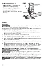
Fig. 26a
Alignment Flange
Sprocket
Guide-bar
Slot
Fastening
Bolt
Fig. 26b
Cutter Direction
5. Place the guide bar on the mounting
surface by sliding the guide-bar slot over
the alignment flanges. Mark sure that the
guide bar is correctly positioned over the
fastening bolt.
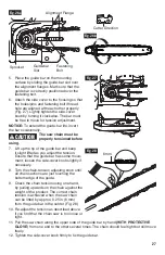
6. Attach the side cover to the housing so that
the holes/pins and fastening bolt /thread
hole are aligned with each other properly
(Fig. 27). Lightly tighten the side-cover
knob by turning it clockwise. The bar must
be free to move for tension adjustment.
NOTICE: To extend the guide-bar life, invert
the bar occasionally.
CAUTION
The saw chain must be
properly tensioned before
using .
7. Lift up the tip of the guide bar and keep
it slight lifted as you adjust the tension.
Ensure that the guide bar has some move-
ment; loosen the side-cover knob slightly if
necessary.
8. Turn the chain-tension adjusting knob until
all chain sections are just touching the
bottom edge of the guide.
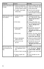
9. Check the chain tension using one hand,
by pulling upwards on the chain against the
weight of the product. The correct chain
tension is achieved when the saw chain
can be lifted by approx. 0.25 in (6 mm)
from the guide bar in the center (Fig. 28).
10. Re-adjust the tension as described above
if you find that the chain saw is too loose or
tight.
11. Pull the saw chain along the upper side of the guide bar by hand (WITH PROTECTIVE
GLOVE) from one end to the other several times. The chain should feel tight but still move
freely.
12. Tighten the side-cover knob firmly to fix the guide bar.
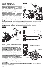
Fig. 27
Fig. 28
6 mm

