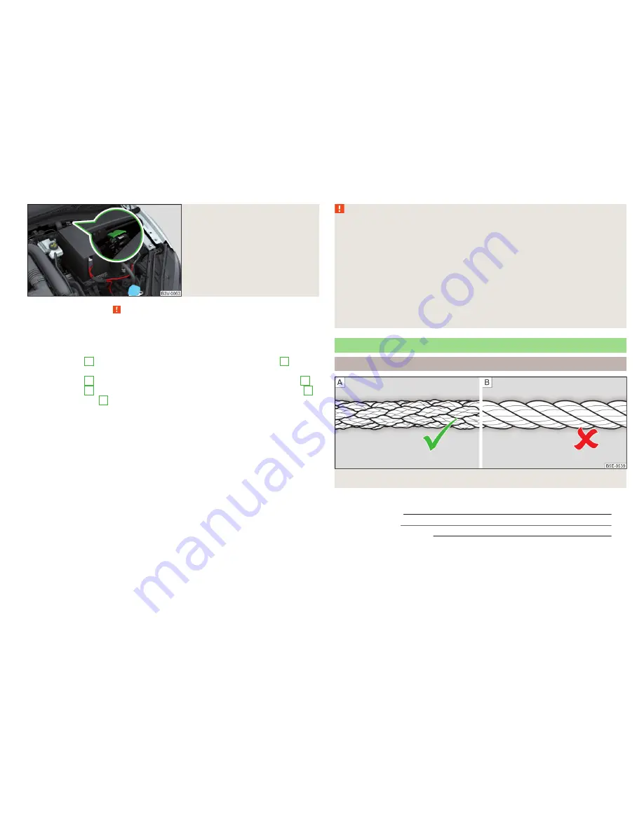
Fig. 250
Engine earth: START-STOP sys-
tem
Read and observe on page 230 first.
The starting process using the battery of another vehicle requires the use of
jumper cables.
The jump-start cables must be attached in the following sequence.
›
Attach clamp
1
to the positive terminal of the discharged battery
A
» Fig. 249
.
›
Attach clamp
2
to the positive terminal of the battery supplying power
B
.
›
Attach clamp
3
to the negative terminal of the battery supplying power
B
.
›
Attach the clamp
4
to a solid metal part which is connected firmly to the en-
gine block or to the engine block itself.
The jump-start cable must be connected to the engine earthing point only on
vehicles with the START-STOP system
» Fig. 250
.
Starting engine
›
Start the engine on the vehicle providing the power and allow it to idle.
›
Start the engine of the vehicle with the discharged battery.
›
If the engine does not start, terminate the attempt to start the engine after
10 seconds and wait for 30 seconds before repeating the process.
›
Remove the jump start cables in the
reverse
order as attachment.
Both batteries must have a rated voltage of 12 V. The
capacity
(Ah) of the bat-
tery supplying the power must not be significantly less than the capacity of
the discharged battery in your vehicle.
Jump-start cables
Only use jump-start cables which have an adequately large cross-section and
insulated terminal clamps. Observe the instructions of the jumper lead manu-
facturer.
Positive cable
- colour coding in the majority of cases is red.
Negative cable
- colour coding in the majority of cases is black.
WARNING
■
Do not clamp the jump-start cable to the negative terminal of the dis-
charged battery. There is the risk of detonating gas seeping out the battery
being ignited by the strong spark which results from the engine being star-
ted.
■
The non-insulated parts of the terminal clamps must never touch each
other – risk of short circuit!
■
The jump-start cable connected to the positive terminal of the battery
must not come into contact with electrically conducting parts of the vehicle
– risk of short circuit!
■
Route the jump-start cables so that they cannot be caught by any rotat-
ing parts in the engine compartment.
Towing the vehicle
Introduction
Fig. 251
Braided tow rope / Spiral tow rope
This chapter contains information on the following subjects:
Front towing eye
232
Rear towing eye
233
Vehicles with a tow hitch
233
For towing, a braided tow rope is to be used
» Fig. 251
-
.
When towing, the following guidelines must be observed.
Vehicles with
manual transmission
may be towed in with a tow bar or a tow
rope or with the front or rear wheels raised.
231
Emergency equipment and self-help
Summary of Contents for 2015 Superb
Page 1: ...SIMPLY CLEVER OWNER S MANUAL OWNER S MANUAL ŠKODA Superb ...
Page 2: ......
Page 28: ...Fig 21 Cockpit 26 Using the system ...
Page 270: ...WLAN see Infotainment 4 X XDS 145 Xenon headlight 69 268 Index ...
Page 271: ...269 Index ...
Page 272: ...270 Index ...
Page 274: ......
Page 275: ......
Page 276: ...www skoda auto com Návod k obsluze Superb anglicky 11 2015 ...


