background image

4

How to Set Up the Scooter

Follow the steps below to set up the scooter for use. Assembly requires the included tool kit.

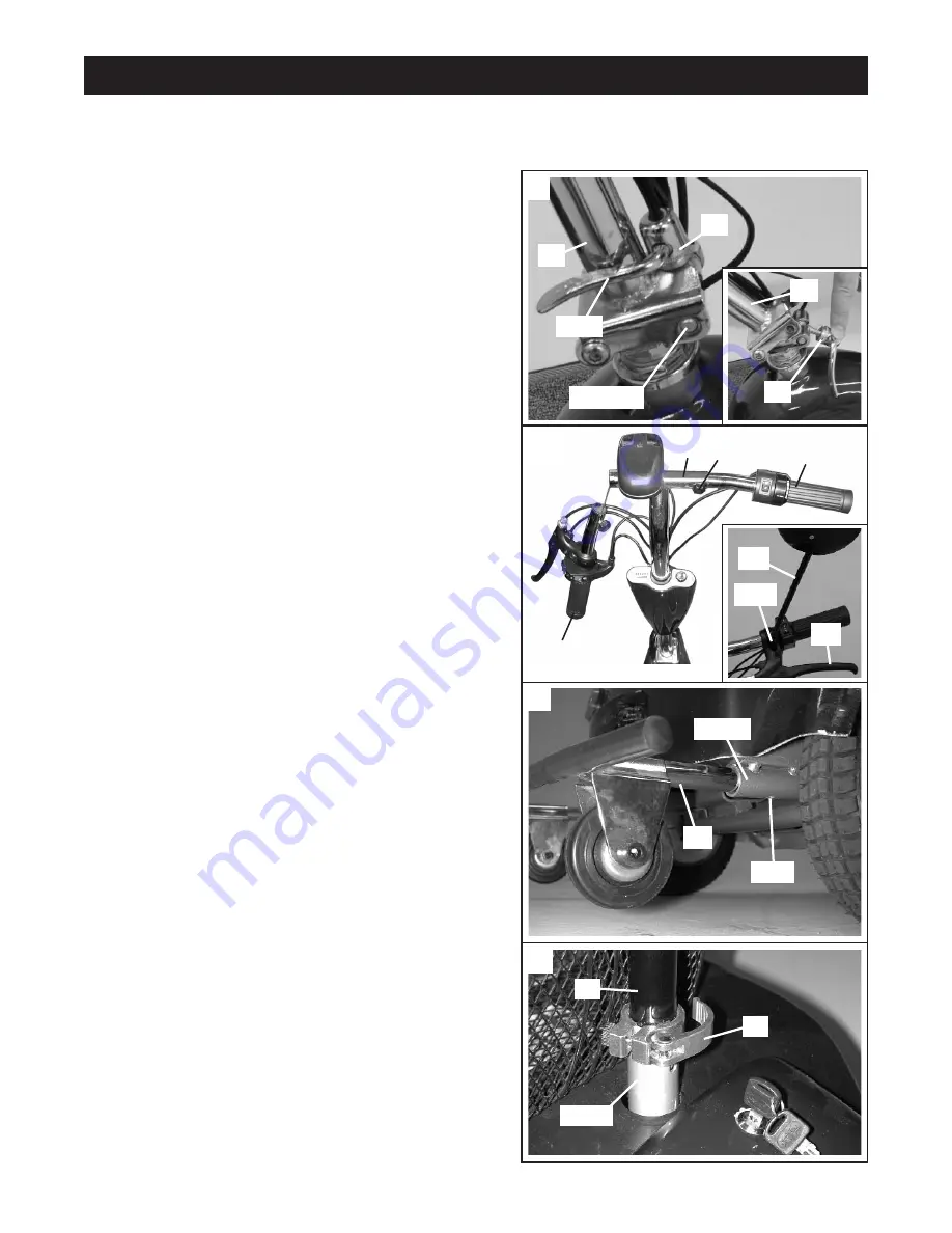
2.

Insert the Right Handlebar (26) into the crossbar on the
Upright (41) as shown. Attach the Right Handlebar by
tightening a Handlebar Screw and Handlebar Washer
(22) into the outer hole in the crossbar.

Attach the Left Handlebar (27) to the crossbar in the
same manner. 

See the inset photograph. Remove the screw (not
shown) from the indicated hole. Tighten the Mirror (24)
into the hole until the Brake Handle (28) is held securely.

3.

Insert the Bumper (8) into the indicated tubes on the
frame. Note: It may be necessary to use a rubber mallet
to fully insert the Bumper.

Tighten a Bumper Screw (not shown) into the indicated
hole in each of the tubes on the frame. 

4.

Open the lever on the Seat Clamp (3). Insert the Seat
Post (2) into the frame. Close the lever on the Seat
Clamp.

2

1.

See the inset photograph. Press and hold down the
Upright Latch (19). While holding down the Upright
Latch, fully raise the Upright (41). 

Raise the Upright Latch (19), making sure that the latch
pins snap securely into the holes in the bracket on the
Upright (41). Securely fasten the Upright Latch by fold-
ing down the lever on the Upright Latch to the position
shown.

3

1

Latch Pin

19

41

41

19

Lever

Hole

Tube

8

Hole

24

28

26

22

41

27

4

2

Frame

3

Summary of Contents for TBSC79020

Page 1: ... for future reference User s Manual Model No TBSC79020 Model No TBSC79920 Table of Contents Important Precautions 2 Before You Begin 3 How to Set Up the Scooter 4 How to Operate the Scooter 6 Maintenance and Troubleshooting 8 Part List 11 How to Order Replacement Parts 11 Limited Warranty Back Cover ...

Page 2: ...seri ous injury or damage to the scooter do not exceed this maximum user weight limit 10 Never ride the scooter on wet or uneven surfaces or when visibility is poor Use the front light in darkened conditions 11 Do not allow more than one person to ride the scooter at a time Never tow another person or vehicle behind the scooter Never allow the scoot er to be towed behind a bicycle motorcycle or ve...

Page 3: ...to familiarize yourself with the parts of the scooter that are labeled in the drawing below A caution decal has been placed on the scooter in the location shown above If the decal is missing or illegible please call our Customer Service Department toll free at 1 800 999 3756 Monday through Friday 6 a m until 6 p m Mountain Time to order a free replacement decal Apply the replacement decal in the l...

Page 4: ...er 8 into the indicated tubes on the frame Note It may be necessary to use a rubber mallet to fully insert the Bumper Tighten a Bumper Screw not shown into the indicated hole in each of the tubes on the frame 4 Open the lever on the Seat Clamp 3 Insert the Seat Post 2 into the frame Close the lever on the Seat Clamp 2 1 See the inset photograph Press and hold down the Upright Latch 19 While holdin...

Page 5: ...r of the fuse holder and open the fuse holder Remove the fuse from the small plastic clips inside of the fuse holder Slide the ends of the red wires onto the ends of the fuse and then press the ends of the red wires into the large plastic clips inside of the fuse holder Close the fuse holder Note An extra fuse can be stored in the fuse holder Close and lock the battery cover 7 Locate the two black...

Page 6: ...ug the battery charger from the charging socket on the scooter For maximum battery life avoid leaving the on off key in the ON position when the scooter is not in use Avoid draining the batteries It is recommended that the batter ies be charged after each use The batteries should be charged at least once each month even if the scooter is not used If the batteries need to be replaced refer to HOW T...

Page 7: ... F The left handlebar has several controls and a rear view mirror for your convenience and safety while riding the scooter See the photograph at the lower left Use the turn signal switch and horn button to signal your inten tions to others The front light switch allows you to turn on the front light in darkened conditions or when visibili ty is poor Adjust the mirror to allow for a clear view of w...

Page 8: ...o tighten the brake or clockwise to loosen it Then turn the locknut clockwise and retighten it Repeat until the brake is properly adjusted If the brake requires further adjustment locate the locknut and adjustment barrel near the lower end of the brake cable Using a small open end wrench loosen the locknut Next turn the adjust ment barrel counterclockwise to tighten the brake or clockwise to loose...

Page 9: ...Notes 9 ...

Page 10: ...10 Notes ...

Page 11: ...1 Signal Light Lens 15 1 Stop Light Lens 16 2 Battery 17 1 Battery Charger 18 1 Carpet Mat 19 1 Upright Latch 20 1 Headlight w Bracket 21 1 On Off Key 22 2 Handlebar Screw w Washer 23 1 Horn 24 1 Mirror 25 2 Bumper Endcap 26 1 Right Handlebar w Throttle 27 1 Left Handlebar w Light Controls 28 1 Brake Handle 29 1 Motor Assembly 30 3 Tire 31 3 Tube 32 1 Chain 33 1 Brake Cable 34 3 Front Wheel Bolt 3...

Page 12: ...orized by ICON ICON is not responsible or liable for indirect special or consequential damages arising out of or in connection with the use or performance of the product or damages with respect to any economic loss loss of property loss of revenues or profits loss of enjoyment or use costs of removal installation or other consequential damages of whatsoever nature Some states do not allow the excl...

Reviews: