background image

9

SKOPE B1200-2/B1200G-2

Operation

User Manual

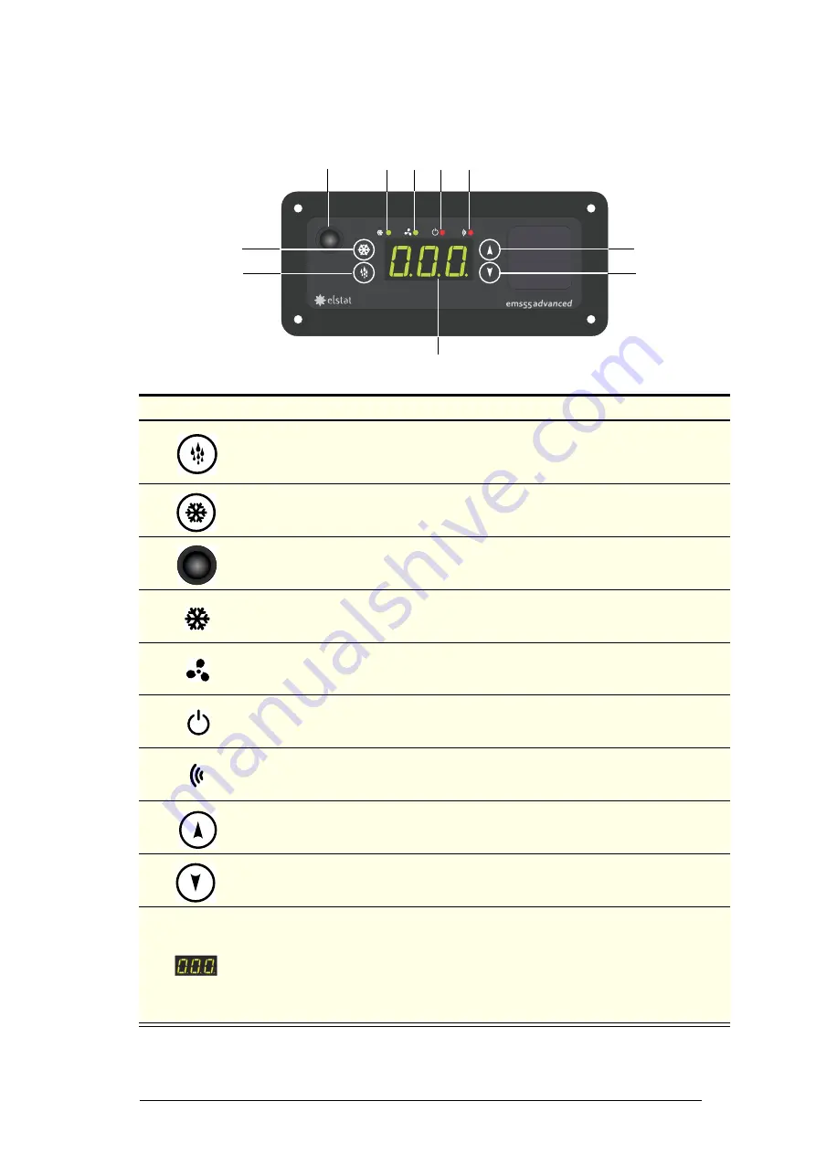
Faceplate

Because the EMS Advanced controller plays such an important role, it’s 
helpful to know the parts of the faceplate you will use.

No.

 Item

Description

1

DEFROST 

button. Manually activates an additional defrost cycle, and used to program 

the controller.

The first automatic defrost occurs six hours after the first off-cycle.

2

SET 

button.


Used to program the controller.

3

Eye of the infrared motion sensor. It detects activity within five metres around the front 
of the chiller, and feeds the data to the EMS advanced controller.

4

LED for the compressor light – green when on.

5

LED for the evaporator fan – green when on.

6

LED indicating perishable mode – red when on. See page 10 for more information.

7

LED linked to the motion sensor and flashes red when there is activity around the 
chiller, but otherwise off.

8

UP 

button. Used to program the controller.

9

DOWN 

button. Used to program the controller.

10

Digital display of cabinet temperature or messages (see next page for details).

The temperature is what the sensor inside the chiller detects, and not necessarily the 
product temperature. However, they may be very close depending on how the 
controller is set to sense temperature. 

When the chiller is in stand-by mode, the controller displays three bars (- - -). This 
should not be displayed during normal business hours.

8

9

1

2

3

4

5

6

7

10

Summary of Contents for B1200-2

Page 1: ...B1200 2 B1200G 2 User Manual MAN10364 Rev 3 3 Mar 2014 B1200G 2 SKOPE Two Door Vertical Chiller B1200 2 no sign G12EV X5621 B1200G 2 lit sign G12EV...

Page 2: ...land SKOPE 1 year Extended Warranty Extend your Warranty Protection by 1 year during registration Please check you have not already organised an extended warranty through your dealer at time of purcha...

Page 3: ...om Shelves 6 Wire Shelves 6 2 Operation Automatic Start Up 7 Loading Product 7 EMS Controller Operations 8 Introduction 8 Self Learning 8 Motion Sensor Door Switch 8 Faceplate 9 Temperature Setpoint 1...

Page 4: ...ssential to economical high performance Be careful not to touch moving parts and hot surfaces For your own safety and that of others ensure that all electrical work is done by authorised personnel If...

Page 5: ...from overflowing Ventilation Ensure there is always at least a 50mm gap around the back top and underside of the cabinet Keep the ventilation slots in the front panel clear at all times never store ca...

Page 6: ...may be fitted at different heights to suit various products Each shelf is held in place with four shelf clips which engage in the shelf support strips The support strips are numbered for easy location...

Page 7: ...elves because this might stop the doors from shutting or even break something Item Activity Condenser Fan The condenser fan starts when the chiller is plugged in Lighting The lights that illuminate th...

Page 8: ...t shopping activity and updating itself A service agent is not required if the store hours change or you disconnect the power to move the chiller The EMS Advanced controller continuously collects data...

Page 9: ...the compressor light green when on 5 LED for the evaporator fan green when on 6 LED indicating perishable mode red when on See page 10 for more information 7 LED linked to the motion sensor and flash...

Page 10: ...ture is moderated the lights switch off and the fans cycle on and off during standby periods resulting in maximum energy savings Follow the steps below to change between perishable and non perishable...

Page 11: ...pen over two minutes an alarm sounds but stops when the door closes again If the door remains open five minutes such as when loading product then the alarm stops and the EMS Advanced controller turns...

Page 12: ...olated from the power supply before cleaning Condenser Coil To ensure trouble free performance we strongly urge monthly cleaning with a soft brush to remove dust and fluff A more thorough cleaning is...

Page 13: ...late the chiller from the mains power supply see previous page 2 Remove the diffuser by squeezing it until it is released from the aluminium housing and then push the diffuser out of the way 3 Rotate...

Page 14: ...of the sign assembly 6 Loosen the two outside screws vertical slot screws and slide the lampholder brackets and LED tube to the bottom of the vertical slots 7 Rotate and remove the failed LED tube 8...

Page 15: ...higher than expected Unit operating too hot Clean the condenser coil see page 12 Ensure the cabinet has good ventilation around the refrigeration unit see page 5 Ensure the cabinet is in a cool spot...

Page 16: ...after their state condition get up or packaging has been altered in any manner Alters removes including part removal or obliterates including part obliteration the trade mark on the product Applies a...

Reviews: