background image

28 

Technische Bedienungsanleitung 


ECT/DCT 632-6 Fans 

INSTALLATIONSANLEITUNG 

Elektrischer Anschluss 


Die Installation, Servicearbeiten und Fehlersuche in Verbindung mit elektrischer Ausrüstung 
muss durch sachkundiges Personal in Übereinstimmung mit geltenden nationalen Vorschriften 
erfolgen.  
In Europa in Übereinstimmung mit EN 60204-1 und sonstigen EU-Vorschriften. 
Versorgungstrenner muss für jeden Motor und Stromversorgung installiert werden, damit 
Servicearbeiten auf elektrischer Ausrüstung in einer spannungslosen Umgebung ausgeführt 
werden können. Der Versorgungstrenner wird nicht von SKOV A/S geliefert.. 


3.1 

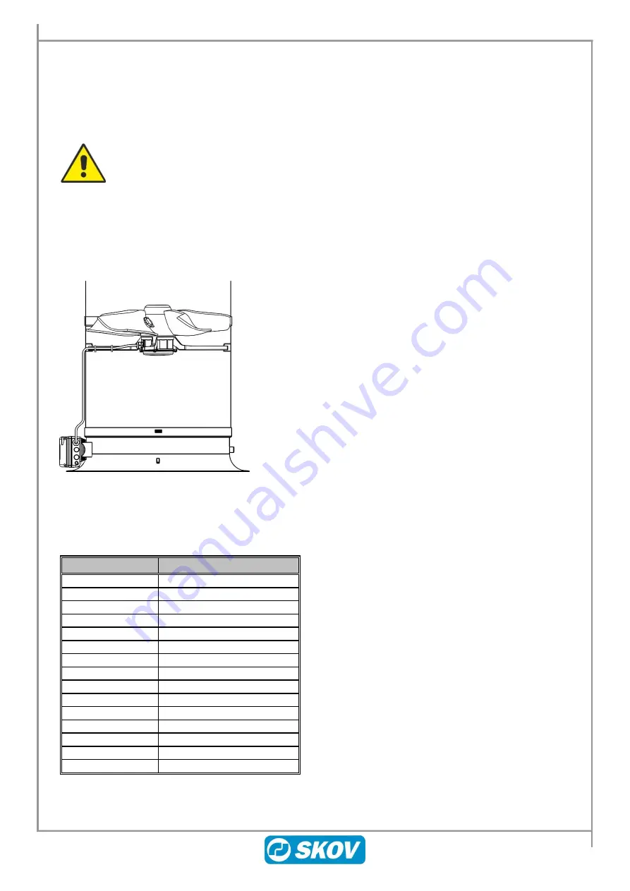
Kabeleinführung 


3.2  Farbcode  

Farbcodes auf den Leitungen nach der Norm IEC 60757: Buchstabcodes zur Inditifikation der Farben die auf 
den Zeichnungen, Diagrammen, Markierung, usw. angewandt werden: 

Buchstabcode 

Farbe 

BK 

Black 

BN 

Brown 

RD 

Red 

OG 

Orange 

YE 

Yellow 

GN 

Green 

BU 

Blue (incl. light blue) 

VT 

Violet (purple red) 

GY 

Grey (slate) 

WH 

White 

PK 

Pink 

GD 

Gold 

TQ 

Turquoise 

SR 

Silver 

GNYE 

Green-and-yellow 


Ein Loch für das Kabel bohren und das Kabel am Schenkel entlang 
an der zum Stellmotor weisenden Seite hinausführen.  

Summary of Contents for DCT 632-6

Page 1: ...2019 01 21 604208 ECT DCT 632 6 Fans ECT DCT 632 6 ventilatorer Teknisk brugervejledning ECT DCT 632 6 fans Technical User Guide ECT DCT 632 6 Ventilatoren Technische Bedienungsanleitung DA EN DE ...

Page 2: ...tervals according to SKOV A S terms and conditions of sale and delivery Note All rights reserved SKOV A S No part of this manual may be reproduced in any manner what soever without the express written permission from SKOV A S SKOV A S has made all reasonable efforts to ensure the accuracy of the information contained in this manual Should any mistakes or imprecise information occur in spite of thi...

Page 3: ... m kabel S409143A 10 5 1 Kabelplan og tilslutning 10 5 2 Kredsskema 10 6 ECT 632 6 ventilator FF 230V 60Hz 409146 11 6 1 Kabelplan og tilslutning 11 6 2 Kredsskema 11 7 DCT 632 6 ventilator FF 3x400 V 409144 og DCT 632 6 ventilator FF 400V 5 m kabel S409144A 12 7 1 Kabelplan og tilslutning 12 7 2 Kredsskema 12 8 DA 40 ECT 632 6 ventilator FF 230V 409154 13 8 1 Kabelplan og tilslutning 13 8 2 Kreds...

Page 4: ... Diagram 20 6 ECT 632 6 Fan FF 230V 60Hz 409146 21 6 1 Cable Plan and connection 21 6 2 Circuit Diagram 21 7 DCT 632 6 Fan FF 3x400 V 409144 and DCT 632 6 Fan FF 400V 5 m cable S409144A 22 7 1 Cable Plan and connection 22 7 2 Circuit Diagram 22 8 DA 40 ECT 632 6 ventilator FF 230V 409154 23 8 1 Cable Plan and connection 23 8 2 Circuit Diagram 23 MAINTENANCE GUIDE 24 9 Cleaning 24 10 Dismantling fo...

Page 5: ...d Anschluss 30 5 2 Schaltplan 30 6 ECT 632 6 Ventilator FF 230V 60 Hz 409146 31 6 1 Kabelplan und Anschluss 31 6 2 Schaltplan 31 7 DCT 632 6 Ventilator FF 3x400 V 409144 und DCT 632 6 Ventilator FF 400V 5 m Kabel S409144A 32 7 1 Kabelplan und Anschluss 32 7 2 Schaltplan 32 8 DA 40 ECT 632 6 Ventilator FF 230V 409154 33 8 1 Kabelplan und Anschluss 33 8 2 Schaltplan 33 WARTUNGSANLEITUNG 34 9 Reinigu...

Page 6: ... end 40 Pa ErP 2015 godkendt 409146 ECT 632 6 ventilator FF 230V 60Hz CSA 5 vinget 230 V 60 Hz regulerbar ventilator med aluminiumsvinger Benyttes både som trinløs triacreguleret ventilator og som ON OFF ventilator Lav investeringsomkostning pr m3 h Høj ydelse og god trykstabilitet fra 0 50 Pa Bør ikke benyttes ved undertryk højere end 50 Pa ErP 2015 godkendt 409144 DCT 632 6 ventilator FF 400V S4...

Page 7: ...er de fire ventilatorophæng med skruer på de nederste markerede positioner Pas på ikke at overspænde skruerne Pas på ventilatorer kan rotere drevet af luftens bevægelse Ventilatoren ligger i skorstensrørets ventilatorophæng uden anden fæstnelse end egenvægten 2 Sikkerhedsafstand Hvis afstanden fra gulv til ventilatorvingen er mindre end 270 cm kan det være et lovmæssigt krav at der monteres sikker...

Page 8: ...kan foregå spændingsløst Forsyningsadskiller leveres ikke af SKOV A S Kontakt SKOV A S service eller forhandler ved tvivlsspørgsmål 3 1 Kabelføring 3 2 Farve kode Farvekode på ledninger i henhold til standard IEC 60757 Bogstavkoder til identifikation af farver anvendt på tegninger skemaer mærkning mv Bogstavkode Farve BK Black BN Brown RD Red OG Orange YE Yellow GN Green BU Blue incl light blue VT...

Page 9: ... 9 ECT DCT 632 6 Fans 4 ECT 632 6 ventilator FF 230V 50Hz 409143 4 1 Kabelplan og tilslutning 4 2 Kredsskema Klemkasse på ventilator Eks på klemmenummer For korrekt tilslutning se opsætningsmenuen Vis tilslutninger i computer ...

Page 10: ...CT DCT 632 6 Fans 5 ECT 632 6 vent FF 230V 5 leder 5 m kabel S409143A 5 1 Kabelplan og tilslutning 5 2 Kredsskema Klemkasse på ventilator Eks på klemmenummer For korrekt tilslutning se opsætningsmenuen Vis tilslutninger i computer ...

Page 11: ... 11 ECT DCT 632 6 Fans 6 ECT 632 6 ventilator FF 230V 60Hz 409146 6 1 Kabelplan og tilslutning 6 2 Kredsskema Klemkasse på ventilator Eks på klemmenummer For korrekt tilslutning se opsætningsmenuen Vis tilslutninger i computer ...

Page 12: ...DCT 632 6 ventilator FF 3x400 V 409144 og DCT 632 6 ventilator FF 400V 5 m kabel S409144A 7 1 Kabelplan og tilslutning 7 2 Kredsskema Klemkasse på ventilator Eks på klemmenummer For korrekt tilslutning se opsætningsmenuen Vis tilslutninger i computer ...

Page 13: ...32 6 ventilator FF 230V 409154 Ved montering i DA 40 skal ventilator vinger vende opad Se afsnit 1 1 8 1 Kabelplan og tilslutning 8 2 Kredsskema Klemkasse på ventilator Eks på klemmenummer For korrekt tilslutning se opsætningsmenuen Vis tilslutninger i computer ...

Page 14: ...eder genbrugsstationer efter lokale anvisninger Genbrugsstationen vil herefter videreformidle produkterne til et godkendt anlæg med henblik på genbrug genvinding og genanvendelse 11 Fejlfindingsvejledning Der må ikke foretages service af ventilatoren før der på forsvarlig vis er afbrudt for strømmen Vent 30 sek med at afmontere låget på motorstyringen eller berøre motorledningerne efter forsynings...

Page 15: ...90 1040 930 890 Luftydelse m3 h ved 10 Pa 12 700 14 900 13 100 7 300 Luftydelse m3 h ved 20 Pa 12 200 14 500 12 700 7 600 Luftydelse m3 h ved 30 Pa 11 700 13 900 12 100 7 900 Luftydelse m3 h ved 40 Pa 10 800 13 400 11 500 8 100 Luftydelse m3 h ved 50 Pa 9 800 12 500 10 500 Effektforbrug W ved 10 Pa 436 692 440 477 Specifik ydelse m3 kWh ved 10 Pa 29 100 21 500 29 800 15 400 Specifik energi Watt 10...

Page 16: ...rP 2015 approved 409146 ECT 632 6 fan FF 230V 60Hz CSA 5 fan blades 230V 60 Hz adjustable fan with aluminium fan blades Can be used both as a stepless triac controlled fan and as an ON OFF fan Low costs per m3 h High output and good pressure stability from 0 50 Pa It should not be used at negative pressure higher than 50 Pa ErP 2015 approved 409144 DCT 632 6 fan FF 400V S409144A DCT 632 6 fan FF 4...

Page 17: ...ur fan suspensions with screws in the bottom marked positions Be careful not to tighten the screws too much Be careful the fan may rotate if gripped by wind The fan is positioned in the fan suspension units of the chimney duct secured only by its own weight 2 Safety Distance If the distance from the floor to the fan blade is less than 270 cm mounting a protective mesh in the inlet bell mouth may b...

Page 18: ...upply so maintenance of electrical equipment can be carried out in a dead environment Supply isolator is not supplied by SKOV A S 3 1 Cabling 3 2 Colour Code Colour code on the wires in appliance with the IEC 60757 standard Alphabetic codes for identification of colours used on drawings diagrams marking etc Bogstavkode Farve BK Black BN Brown RD Red OG Orange YE Yellow GN Green BU Blue incl light ...

Page 19: ...19 ECT DCT 632 6 Fans 4 ECT 632 6 Fan FF 230V 50Hz 409143 4 1 Cable Plan and connection 4 2 Circuit Diagram Terminal box on the fan Ex of terminal number For correct connection see the setup menu Show connection in computer ...

Page 20: ...CT 632 6 Fans 5 ECT 632 6 fan FF 230V five core 5m cable S409143A 5 1 Cable Plan and connection 5 2 Circuit Diagram Terminal box on the fan Ex of terminal number For correct connection see the setup menu Show connection in computer ...

Page 21: ...21 ECT DCT 632 6 Fans 6 ECT 632 6 Fan FF 230V 60Hz 409146 6 1 Cable Plan and connection 6 2 Circuit Diagram Terminal box on the fan Ex of terminal number For correct connection see the setup menu Show connection in computer ...

Page 22: ...7 DCT 632 6 Fan FF 3x400 V 409144 and DCT 632 6 Fan FF 400V 5 m cable S409144A 7 1 Cable Plan and connection 7 2 Circuit Diagram Terminal box on the fan Ex of terminal number For correct connection see the setup menu Show connection in computer ...

Page 23: ...tilator FF 230V 409154 When installed in DA 40 the fan blades must be turned upwards See section 1 1 8 1 Cable Plan and connection 8 2 Circuit Diagram Terminal box on the fan Ex of terminal number For correct connection see the setup menu Show connection in computer ...

Page 24: ...ng points recycling stations according to local directions The recycling station will then send the products to an approved plant for recycling and reuse 11 Troubleshooting Guide Always disconnect the power securely before servicing the fan When the control voltage has been disconnected wait for 30 sec before removing the lid of the motor control or touching the motor cables Symptom Løsning The fa...

Page 25: ...h at 10 Pa 12 700 14 900 13 100 7 300 Air output m3 h at 20 Pa 12 200 14 500 12 700 7 600 Air output m3 h at 30 Pa 11 700 13 900 12 100 7 900 Air output m3 h at 40 Pa 10 800 13 400 11 500 8 100 Air output m3 h at 50 Pa 9 800 12 500 10 500 Power consumption W at 10 Pa 436 692 440 477 Specific output m3 kWh at 10 Pa 29 100 21 500 29 800 15 400 Specific energy Watt 1000 m3 h at 10 Pa 34 47 34 65 Test...

Page 26: ...tor FF 230V 60Hz CSA 5 geflügelter 230 V 60 Hz regelbarer Ventilator mit Aluminiumflügeln Wird sowohl als stufenloser Triac geregelter Ventilator als auch ON OFF Ventilator eingesetzt Niedrige Investitionskosten pro m3 h Hohe Leistung und gute Druckstabilität von 0 50 Pa Darf bei Unterdruck höher als 50 Pa nicht eingesetzt werden Mit ErP 2015 Zulassung 409144 DCT 632 6 Ventilator FF 400V S409144A ...

Page 27: ...ier Ventilatoraufhängungen mit Schrauben in den unten gekennzeichneten Positionen Achten Sie darauf die Schrauben nicht zu fest zu ziehen Es ist zu prüfen dass der Ventilator je nach Ventilatortyp in die richtige Richtung zeigt Achtung Der Ventilator kann durch Luftbewegungen rotieren 2 Sicherheitsabstand Wenn der Abstand vom Boden zum Ventilator weniger als 270 cm beträgt muss möglicherweise laut...

Page 28: ...eiten auf elektrischer Ausrüstung in einer spannungslosen Umgebung ausgeführt werden können Der Versorgungstrenner wird nicht von SKOV A S geliefert 3 1 Kabeleinführung 3 2 Farbcode Farbcodes auf den Leitungen nach der Norm IEC 60757 Buchstabcodes zur Inditifikation der Farben die auf den Zeichnungen Diagrammen Markierung usw angewandt werden Buchstabcode Farbe BK Black BN Brown RD Red OG Orange Y...

Page 29: ...T DCT 632 6 Fans 4 ECT 632 6 Ventilator FF 230V 50Hz 409143 4 1 Kabelplan und Anschluss 4 2 Schaltplan Klemmkasten an dem Ventilator Bsp für Klemmennummer Zum korrekten Anschluss siehe Installationsmenü Installation anzeigen beim computer ...

Page 30: ...T 632 6 Fans 5 ECT 632 6 Vent FF 230V fünfadrig Kabel S409143A 5 1 Kabelplan und Anschluss 5 2 Schaltplan Klemmkasten an dem Ventilator Bsp für Klemmennummer Zum korrekten Anschluss siehe Installationsmenü Installation anzeigen beim computer ...

Page 31: ... DCT 632 6 Fans 6 ECT 632 6 Ventilator FF 230V 60 Hz 409146 6 1 Kabelplan und Anschluss 6 2 Schaltplan Klemmkasten an dem Ventilator Bsp für Klemmennummer Zum korrekten Anschluss siehe Installationsmenü Installation anzeigen beim computer ...

Page 32: ...2 6 Ventilator FF 3x400 V 409144 und DCT 632 6 Ventilator FF 400V 5 m Kabel S409144A 7 1 Kabelplan und Anschluss 7 2 Schaltplan Klemmkasten an dem Ventilator Bsp für Klemmennummer Zum korrekten Anschluss siehe Installationsmenü Installation anzeigen beim computer ...

Page 33: ...F 230V 409154 Bei Einbau in DA 40 müssen die Ventilatorflügel nach oben gedreht werden Siehe Abschnitt 1 1 8 1 Kabelplan und Anschluss 8 2 Schaltplan Klemmkasten an dem Ventilator Bsp für Klemmennummer Zum korrekten Anschluss siehe Installationsmenü Installation anzeigen beim computer ...

Page 34: ...tungseinrichtungen vor Ort laut regionaler Vorschriften abgeben Die Wiederverwertungsstellen vermitteln die Produkte an eine zugelassene Anlage zur Wiederverwertung Wiedergewinnung 11 Fehlersucheanleitung Am Ventilator dürfen erst dann Wartungsarbeiten ausgeführt werden wenn er sicher vom Stromnetz getrennt ist Nach dem Abschalten der Versorgungsspannung sollte etwa 30 Sekunden gewartet werden bev...

Page 35: ...ennzeichen 890 1040 930 890 Luftleistung m3 h bei 10 Pa 12 700 14 900 13 100 7 300 Luftleistung m3 h bei 20 Pa 12 200 14 500 12 700 7 600 Luftleistung m3 h bei 30 Pa 11 700 13 900 12 100 7 900 Luftleistung m3 h bei 40 Pa 10 800 13 400 11 500 8 100 Luftleistung m3 h bei 50 Pa 9 800 12 500 10 500 Effektforbrug W bei 10 Pa 436 692 440 477 Spezifische Leistung m3 kWh bei 10 Pa 29 100 21 500 29 800 15 ...

Page 36: ...SKOV A S Hedelund 4 Glyngøre DK 7870 Roslev Tel 45 72 17 55 55 Fax 45 72 17 59 59 www skov com E mail skov skov dk 2019 01 21 604208 04 03 04 DA EN DE Made in Denmark ...

Reviews: