27
ASSEMBLY STEPS
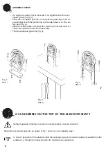
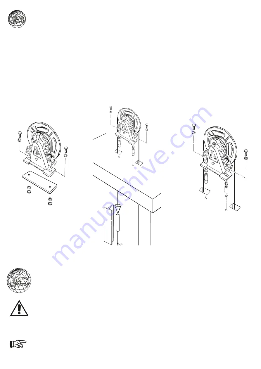
• If a support s used, first of all screw t on together w th the over-
speed governor (fig. 1).
• Place the overspeed governor on the pass ng open ng of the ro-
pe and al gn t w th the plumb l ne to the brake dev ce, .e. the sa-
fety gear (fig. 2).
• Mark the dr lled holes and place the nserts (the nserts must re-
s st to the operat on load of at least 2 kN).
• F x the overspeed governor (fig. 3).
F g. 1
Abb. 1
F g. 2
Abb. 2
F g. 3
Abb. 3
2.1.2 ASSEMBLY ON THE TOP OF THE ELEVATOR SHAFT
Safety measures, referr ng to works on elevator plants, must be observed.
Mount the overspeed governor as shown n fig. 1 and 2 (or n an oppos te way).
In case of assembly n the elevator shaft, the overspeed governor must be eas ly access ble from the
outs de (e.g. through an nspect on door for ma ntenance operat ons).
10


