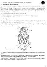
TENSION PULLEY WITH HORIZONTAL COUNTERWEIGHT
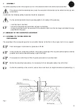
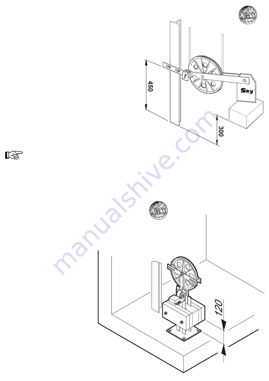
• Mount the mount ng support at about 450 mm (ap-
prox. value, fig. 3) on the bottom of the shaft.
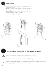
• Hold the counterwe ght, unt l t s n an obl que pos -
t on (fig. 3).
• In the presence of a brake mechan sm act ng up-
wards, mount the second rope-end to the rope-an-
chor of the brake dev ce
or:
• Supply the second rope-end w th the rope-anchor
and attach t to the safety gear.
• Remove the support n order to stretch the rope.
If the assembly has been properly carr ed
out, the counterwe ght should take a sl ghty
upward angled pos t on (fig. 3).
TENSION PULLEY WITH VERTICAL COUNTERWEIGHT
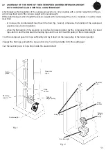
• Mount the lead ng plate of the
counterwe ght to ach eve per-
fect al gnment between the
pulley of the overspeed gover-
nor and the pulley of the ten-
s on we ght (fig. 4).
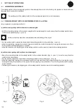
• Hold the counterwe ght, unt l t
reaches a he ght of about 120
mm from the bottom of the
shaft (approx.value) (fig. 4).
F g. 3
F g. 4
10KG
12


